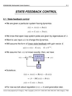
Transcription of Equivalent-Circuit Cell Models
1 ECE4710/5710: Modeling, Simulation, and Identification ofBattery Dynamics2 1 Equivalent-Circuit Cell : Open-circuit voltage and state of charge We begin our study of battery Models by building up behavioral/phenomenological analogs using common circuit elements. The resulting equivalent circuit Models will be helpful in getting afeel for how cells respond to different usage scenarios, andareadequate for some application design as well. Ultimately, however, we will need a deeper physical understanding ofhow the cells work. The rest of the course will focus on voltage (OCV) We start with the simplest possible model. An ideal battery ismodeled as an ideal voltage source. In this model, voltage is not a function of current, voltage is not a function of past usage, voltage is constant. (t)i(t) ++ This model is inadequate, but provides a starting point. Batteriesdosupply a voltage to a load. And, when the cell is unloaded and in complete equilibrium ( , opencircuit ), the voltage is fairly predictable.
2 An ideal voltage source will be part of our Equivalent-Circuit notes prepared by Dr. Gregory L. Plett. Copyright 2011 2018, Gregory L. PlettECE4710/5710, Equivalent-Circuit Cell Models2 2 State of Charge When a cell is fully charged, its open-circuitvoltage is higher than when it is discharged. So, we can improve our model by including adependence on the charge status of the (z(t))v(t)i(t) ++ We define the state of charge (SOC)z(t)of a cell to be:1 When the cell is fully charged,z=100%; Also,z=0%when the cell is fully discharged. We define the total capacityQof a cell to be the total amount ofcharge removed when discharging a cell fromz=100%toz=0%. Qis usually measured in Ah or mAh. We can model SOC as (where z=dz/dt) z(t)= i(t)/Qz(t)=z(t0) 1 QZtt0i( )d ,where the sign ofi(t)is positive on discharge. In discrete time, if we assume that current is constant over samplinginterval1t,z[k+1]=z[k] i[k]1t/Q. Note that cells are not perfectly efficient.
3 We can accommodate thisfact by including an efficiency factor (t) z(t)= i(t) (t)/Qz[k+1]=z[k] i[k] [k]1 will be more precise in our definitions later. But, these will suffice for notes prepared by Dr. Gregory L. Plett. Copyright 2011 2018, Gregory L. PlettECE4710/5710, Equivalent-Circuit Cell Models2 3 The term [k]is called coulombic efficiency. We model [k] 1on charge, as some charge is typically lost dueto unwanted side reactions. We usually model [k]=1on discharge. Don t confuse coulombic (or charge) efficiency with energy efficiency. Coulombic efficiency in a typical lithium-ion cell is around99%andis equal to (charge out)/(charge in). Energy efficiency is closer to 95%, and is equal to (energyout)/(energy in). Energy is lost in resistive heating, but charge is not lost. OCV is plotted as a function ofSOC for several lithium-ionchemistries. Note that OCV is also a functionof temperature we can includethat in the model asOCV(z(t),T(t)).
4 (V)SOC (%)OCV for different chemistries at 25 C Also note that depthofdischarge or DOD is the inverse of SOC: DOD=1 SOC if it is being expressed as a fraction. DOD is sometimes expressed in Ah: DOD=Q(1 SOC). So, it s possible to plot OCV curves versus DOD as well as notes prepared by Dr. Gregory L. Plett. Copyright 2011 2018, Gregory L. PlettECE4710/5710, Equivalent-Circuit Cell Models2 : Linear polarizationEquivalent series resistance A cell s voltage drops when it is under load. This can be modeled, in part, as a resistancein series with the ideal voltage sourcev(t)=OCV(z(t)) i(t) (z(t))v(t) ++R0 Note thatv(t) >OCV(z(t))on charge, andv(t) <OCV(z(t))ondischarge. This implies that power is dissipated by the resistorRas heat, andtherefore that energy efficiency is not perfect. This model is sufficient for many simple electronic circuit designs, butnot for advanced consumer electronics and xEV voltages Polarization refers to any departure of the cell s terminalvoltage awayfrom open-circuit voltage due to a passage of current.
5 I(t) R0is one example ofpolarization, modeling aninstantaneous response to achange in input current. In practice, we also observe adynamic (non-instantaneous)response to a current (min) voltage (V)Polarization visible during discharge and rest Lecture notes prepared by Dr. Gregory L. Plett. Copyright 2011 2018, Gregory L. PlettECE4710/5710, Equivalent-Circuit Cell Models2 5 Similarly, when a cell is allowed to rest, its voltage does notimmediately return to OCV, but decays gradually (sometimestakingan hour or more to approach OCV). We will find out later that this phenomena is caused by slow diffusionprocesses in the cell, so we will refer to this slowly-changing voltageas a diffusion voltage . Its effect can be closely approximatedin a circuit using one or more parallelresistor-capacitor sub-circuits. The cell voltage is modeled asv(t)=OCV(z(t)) vC1(t) i(t) (z(t))R0v(t)R1C1 ++ When using data to identify model parameters, it becomes simpler ifwe write this expression in terms of element currents instead:v(t)=OCV(z(t)) R1iR1(t) R0i(t).
6 To find an expression for theiR1(t), we recognize that the currentthroughR1plus the current throughC1must be equal toi(t). Further,iC1(t)=C1 vC1(t), which givesiR1(t)+C1 vC1(t)=i(t). Then, sincevC1(t)=R1iR1(t),iR1(t)+R1C1diR1(t)d t=i(t)diR1(t)dt= 1R1C1iR1(t)+1R1C1i(t). This differential equation can be simulated as-is to determineiR1(t).We ll see how to convert to discrete-time, notes prepared by Dr. Gregory L. Plett. Copyright 2011 2018, Gregory L. PlettECE4710/5710, Equivalent-Circuit Cell Models2 6 Warburg impedance In the literature, it is not uncommon to see Equivalent-Circuit modelscontaining a so-called Warburg impedance element,ZW. For example, theRandles circuit(shown without OCV) is based onelectrochemical principles, a bit likewe will see in later In the circuit, Rsmodels the electrolyte resistance, Rctis thecharge-transfer resistancethat Models the voltage dropover the electrode electrolyte interface due to a load, Cdlis thedouble-layer capacitancethat Models the effect ofcharges building up in the electrolyte at the electrode surface, and ZWis the Warburg impedance.
7 The frequency-dependent Warburg impedanceZW=AW/pj Models diffusion of lithium ions in the electrodes. The phase contributed to thecircuit by this element is45 ,which is most easily observed ina Nyquist plot of a cell selectrochemical impedancespectrum as a straight line at45 at low impedanceReal(Z), (m ) Imag(Z), (m ) The figure shows a simulated electrochemical impedance spectrumrepresenting a realistic notes prepared by Dr. Gregory L. Plett. Copyright 2011 2018, Gregory L. PlettECE4710/5710, Equivalent-Circuit Cell Models2 7 The equivalent series resistanceR0for this cell is about m ,found as the infinite-frequency impedance. The low-frequency impedance is represented by the straightline at45 , and Models lithium diffusion in the solid particles. At mid-range frequencies, the semi-circular loop is causedby charge-transfer dynamics, which can be modeled as a single R C pair. There is no simple differential-equation representation of a Warburgimpedance, which makes precise circuit simulation intractable.
8 However, it is possible to reproduce the effect of a Warburgimpedance employing multiple resistor capacitor networks in For an exact equivalence, an infinite number of resistor capacitornetworks are needed; but, the circuit can often be modeled very wellover some frequency range using a small number of R C pairs. The double-layer capacitance is often omitted as it has little impact onthe Randles circuit performance except at very high frequencies. WithCdlremoved from the circuit, and the Warburg impedancereplaced by a small finite number of R C circuits, the cell modelcollapses to the one we have already seen, with additional R C pairs. When we discuss implementation of physics-based Models that havethis type of impedance relationship intrinsically built in, we will seehow to automatically create ODEs that accurately model the notes prepared by Dr. Gregory L. Plett. Copyright 2011 2018, Gregory L. PlettECE4710/5710, Equivalent-Circuit Cell Models2 : Converting to discrete time The R C Models we have seen to date are expressed in continuoustime as ordinary differential equations.
9 We wish to convert them to discrete-time ordinary differenceequations (ODEs) for easier use in a final application. We start by deriving a generic process, which we will then apply tothe equation we ve seen. Consider x(t)=ax(t)+bu(t)x(t)=eatx(0)+Zt0ea(t )bu( )d |{z}convolution. How did we get this result?1. x(t) ax(t)=bu(t). at[ x(t) ax(t)]=ddt[e atx(t)]=e atbu(t). [e a x( )]d =e atx(t) x(0)=Zt0e a bu( )d . We wish to evaluatex(t)at discrete timesx[k] =x(k1t). So then,x[k+1]=x((k+1)1t)=ea(k+1)1tx(0)+Z(k +1)1t0ea((k+1)1t )bu( )d . With malice aforethought, break up the integral into two [k+1]=ea1teak1tx(0)+Zk1t0ea((k+1)1t )bu( )d +Z(k+1)1tk1tea((k+1)1t )bu( )d Lecture notes prepared by Dr. Gregory L. Plett. Copyright 2011 2018, Gregory L. PlettECE4710/5710, Equivalent-Circuit Cell Models2 9=ea1teak1tx(0)+Zk1t0ea1tea(k1t )bu( )d +Z(k+1)1tk1tea((k+1)1t )bu( )d =ea1tx(k1t)+Z(k+1)1tk1tea((k+1)1t )bu( )d =ea1tx[k]+Z(k+1)1tk1tea((k+1)1t )bu( )d.
10 Assumeu( )is constant fromk1tto(k+1)1tand equal tou(k1t)x[k+1]=ea1tx[k]+ea(k+1)1t Z(k+1)1tk1te a d bu[k]=ea1tx[k]+ea(k+1)1t 1ae a (k+1)1tk1t!bu[k]=ea1tx[k]+1aea(k+1)1t e ak1t e a(k+1)1t bu[k]=ea1tx[k]+1a ea1t 1 bu[k]. To use this result for the ODE describing the R C circuit,a= 1R1C1,b=1R1C1,x[k]=iR1[k],andu[k]=i[k]. Substituting these values into the generic result, we getiR1[k+1]=exp 1tR1C1 iR1[k]+( R1C1) exp 1tR1C1 1 1R1C1 i[k]=exp 1tR1C1 iR1[k]+ 1 exp 1tR1C1 i[k].Lecture notes prepared by Dr. Gregory L. Plett. Copyright 2011 2018, Gregory L. PlettECE4710/5710, Equivalent-Circuit Cell Models2 10 Ballparking parameters Note that if a single parallel R C branch is in the model, it isquitesimple to get a ballpark idea of the parameter values. First, conduct a pulse test on thecell, similar to the one shown atthe beginning of Topic The immediate jump in voltageat the application of the currentpulse is1v0=R01i, from whichwe can (min) voltage (V)Polarization visible during discharge and rest 1v0=R01i1v =(R0+R1)1i 4R1C1 The steady-state voltage change, is1v =(R0+R1)1i, from whichwe can deduceR1.