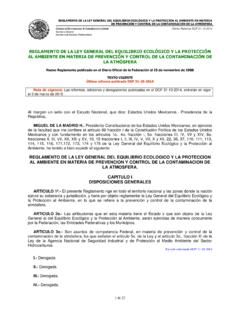
Transcription of EXHAUST GAS PRESSURE SENSOR SENSOR …
1 EXHAUST GAS PRESSURE SENSORSENSOR PRESI N GASES DE ESCAPECAPTEUR DE PRESSION POUR GAZ D CHAPPEMENTTECHNICAL INFORMATIONINFORMACI N T CNICAINFORMATION TECHNIQUE46 TECHNICAL INFORMATIONEXHAUST GAS PRESSURE SENSORThe EXHAUST Gas PRESSURE SENSOR is a differential SENSOR measuring the PRESSURE difference between gas in the intake and the outtake of the Particulate Filter. The outtake may be directly set to ambient PRESSURE depending on the SENSOR is another element in the pollution regulation systems for Diesel engines imposed by European emissions are currently two different systems where the SENSOR is found:- Diesel Particulate Filter Systems with no additive (DPF)- Diesel Particulate Filter Systems with additive (FAP) 1- Dashboard Control unit 1- Dashboard Control unit 2- Engine Control Unit 2- Engine Control Unit 3- Mass Airflow SENSOR 3- Additive Tank 4- Diesel Engine
2 4- Additive level SENSOR 5- Turbo compressor Temperature SENSOR 5- Additive Pump 6- Turbo compressor 6- Fuel Tank 7- Particulate Filter Temperature SENSOR 7- Diesel engine 8- Lambda SENSOR 8- Turbo compressor Temperature SENSOR 9- Particulate Filter 9- Turbo compressor 10- EXHAUST Gas PRESSURE SENSOR 1 10- Lambda SENSOR 11- Post-Particulate Filter Temperature SENSOR 11- Oxidation Catalytic Converter 12- Muffler 12- Particulate Filter Temperature SENSOR 13- Particulate Filter
3 14- EXHAUST Gas PRESSURE SENSOR 1 15- Muffler 16- Mass Airflow SensorBoth systems differentiate on how the filter is regenerated after saturation:On DPF regeneration is done regularly by increasing EXHAUST gas temperature. This is achieved by a post injection process with crankshaft at 35 after Top Dead Point. This way the Filter temperature gets up to 600 C, where soot is burnt.
4 On FAP regeneration is done regularly by mixing an additive in the oil. The additive lowers the soot burning point down to 300-350 C, where soot is burnt. This cycle repeats every 500-700km (varies upon driving style) and lasts from 5 to 10 minutes. The filter saturation level is controlled 1) by the EXHAUST Gas PRESSURE SENSOR , 2) by The Temperature Sensors placed before and after the filter and 3) by the intake Mass Airflow SENSOR . SaturatedEmptyCrashedVolume flow (m3/h)Pression Difference p (mbar)0501001502002503000100200300400500 600700 TECHNICAL INFORMATIONINFORMACI N T CNICAINFORMATION TECHNIQUE47 TECHNICAL INFORMATIONThe EXHAUST PRESSURE sensors need to operate in critical assembly conditions, and need to be operative in temperatures ranging from -40 to +130 C. They also have to be hydrocarbon resistant. In order to achieve this, FAE performs intensive homologations tests including:- Cyclic operation at high and low pressures in extreme environmental Vibration and shock Over PRESSURE operation at high and low Humidity and Temperature Thermal shock from -40 to +150 of our sensors are tested in production against leakage and for precise output voltage ELEMENTThe sensing element of the EXHAUST Gas PRESSURE SENSOR is a piezoresistive on in a Wheatstone Bridge configuration.
5 This SENSOR is basically changing its electrical resistance upon mechanical deformation of the membrane. The sensing element is integrated in a MEMS die including amplification, thermal compensation and signal conditioning. The embedded digital electronics allows programming of the output signal from 0 to die is assembled on a ceramic circuit and the electrical connection is made by wire bonding. The whole system is protected by a receptacle and a silicone gel. The electronics is made by using Hybrid technology and is handled in clean ESD protected room to protect it from unwanted electrical EXHAUST PRESSURE SENSOR output is linear and depends on the PRESSURE difference between input and output. This relationship can be expres-sed with the following formula: Vout = S* P+Of whereas: Vout: Output voltage (V) S.
6 Sensitivity P: PRESSURE difference between filter input and output (kPa) Of: Offset Technical data- Supply voltage: 5 V V - Temperature range: -20 a 130 C (inside tolerance)- Max and Min Temperatures: -40 a 150 C- Response time (t 10/90): Max PRESSURE : 400kPa (30 C for 5s)All these figures are common for all FAE EXHAUST PRESSURE Sensors.
7 Every part has its specific working curve and ,54,55 PRESSURE in KPaOutput Voltage U in VPressure before the filter = PRESSURE after the filterElements piezo-electricsPressure before the filter > PRESSURE after the filterDiaphragm withpiezo-electric elementsPressure before the filterPressure after the filterSignal to the control unitTECHNICAL INFORMATIONINFORMACI N T CNICAINFORMATION TECHNIQUE48 TECHNICAL INFORMATIONSENSOR COMPONENTSThe EXHAUST PRESSURE SENSOR is built with the following components: 1- Sensing element: Electronic circuit over ceramics Body: Molded with PBT+30GF, contains all the parts and has two air Pins: Tin soldered by automated Lid: To grant air tightness. In the sensing element:A- Electronic Ceramics Die Silicon resin (to protect the electronics).E- INSTRUCTIONS- Power off the Locate the SENSOR (following the pipes coming out of the Particulate Filter).
8 - Disconnect PRESSURE pipes (input and Output).- Disconnect SENSOR Extract fixation screws or whatever the holding mechanism Install replacement Connect pipes and electrical INSPECTION / FAILURE CAUSESS ensor body, connector and wiring must be in good condition. Check for bumps, cracks or housing inspection can help but it is not enough to determine if the SENSOR is operating causes can be:- Breaks, pores or cracks in the Wear signs in the connector or Damage of the sensing element causing bad PRESSURE Air leakage in the Wear in the joints between the SENSOR and the of the SENSOR can cause any of the following symptoms:- Unnecessary filter Power losses if the SENSOR is not detecting the filter saturation Dashboard light for Particulate filter (or preheating in some models) and blinking light for Reduction of filter lifespan due to unnecessary Increase in oil Increase in pollution filter outputPressure input filter3124 Camera input pressureCamera output pressureTECHNICAL INFORMATIONINFORMACI N T CNICAINFORMATION TECHNIQUE49 INFORMACI N T CNICASENSOR DE PRESI N PARA LOS GASES DE ESCAPEEl SENSOR de Presi n para los gases de escape, es un SENSOR de presi n diferencial que se encarga de medir la diferencia de presi n que hay en los gases de escape, entre la entrada y la salida del filtro de part culas, o la presi n atmosf rica.
9 El SENSOR de Presi n diferencial, es un elemento m s del sistema anticontaminaci n que llevan los motores di sel para cumplir con la normativa Europea de emisiones dos sistemas donde encontramos el SENSOR de presi n para gases de escape:- Sistemas de filtro de part culas sin aditivo (DPF)- Sistemas de filtro de part culas con aditivo (FAP) 1- Unidad de control en cuadro de instrumentos 1- Unidad de control en el cuadro de instrumentos 2- Unidad de control del motor 2- Unidad de control del motor 3- Medidor de la masa de aire 3- Dep sito de aditivo 4- Motor di sel 4- SENSOR de falta de aditivo para el combustible 5- SENSOR de temperatura ante el turbocompresor 5- Bomba de aditivo para combustible 6- Turbocompresor 6- Dep sito de combustible 7- SENSOR de temperatura ante el filtro de part culas 7- Motor di sel 8- Sonda Lambda 8- SENSOR de temperatura antes de turbocompresor 9- Filtro de part culas
10 9- Turbo compresor 10- SENSOR de presi n 1 para gases de escape 10- Sonda Lambda 11- SENSOR de temperatura despu s de filtro de part culas 11- Catalizador de oxidaci n 12- Silenciador 12- SENSOR de temperatura ante filtro de part culas 13- Filtro de part culas 14- SENSOR de presi n 1 para gases de escape 15- Silenciador 16- Medidor de la masa de aireLa diferencia entre los dos sistemas es la forma como se regenera el filtro cuando el sistema detecta que est el DPF se produce la regeneraci n a trav s de un aumento de la temperatura de los gases de escape, realizando una post-inyecci n a 35 del cig e al despu s del punto muerto superior, para alcanzar los 600 C necesarios para la combusti n lenta de la el FAP, la regeneraci n del filtro se hace de forma sistem tica, de manera que el aditivo baja la temperatura de i