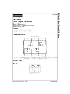
Transcription of FDMS86101 N-Channel PowerTrench® MOSFET
1 April 2016 2013 Fairchild Semiconductor CorporationFDMS86101 N-Channel powertrench MOSFETFDMS86101 N-Channel powertrench MOSFET 100 V, 60 A, 8 m Features Max rDS(on) = 8 m at VGS = 10 V, ID = 13 A Max rDS(on) = m at VGS = 6 V, ID = A Advanced Package and Silicon combination for low rDS(on) and high efficiency MSL1 robust package design 100% UIL tested 100% Rg tested RoHS CompliantGeneral DescriptionThis N-Channel MOSFET is produced using Fairchild Semiconductor s advanced Power Trench process that has been especially tailored to minimize the on-state resistance and yet maintain superior switching DC-DC ConversionBottom Power 56 TopPin 1 GSSSDDDDDDDDSSSGMOSFET Maximum Ratings TA = 25 C unless otherwise noted Thermal CharacteristicsPackage Marking and Ordering InformationSymbolParameterRatingsUnitsVD SD rain to Source Voltage100 VVGSGate to Source Voltage 20 VIDD rain Current
2 -Continuous TC = 25 C 60A -Continuous TA = 25 C (Note 1a) -Pulsed200 EASS ingle Pulse Avalanche Energy (Note 3)173mJPDP ower Dissipation TC = 25 C104 WPower Dissipation TA = 25 C (Note 1a) , TSTGO perating and Storage Junction Temperature Range-55 to +150 CR JCThermal Resistance, Junction to C/WR JAThermal Resistance, Junction to Ambient (Note 1a)
3 50 Device MarkingDevicePackageReel SizeTape WidthQuantityFDMS86101 FDMS86101 Power 5613 12 mm3000 2013 Fairchild Semiconductor CorporationFDMS86101 N-Channel powertrench MOSFETE lectrical Characteristics TJ = 25 C unless otherwise notedOff CharacteristicsOn Characteristics Dynamic CharacteristicsSwitching Characteristics Drain-Source Diode CharacteristicsSymbolParameterTest ConditionsMinTypMaxUnitsBVDSSD rain to Source Breakdown VoltageID = 250 A, VGS = 0 V100 V BVDSS TJBreakdown Voltage TemperatureCoefficientID = 250 A, referenced to 25 C 66 mV/ CIDSSZero Gate Voltage Drain CurrentVDS = 80 V, VGS = 0 V800nAIGSSGate to Source Leakage Current, ForwardVGS = 20 V, VDS = 0 V 100nAVGS(th)Gate to Source Threshold VoltageVGS = VDS, ID = 250 VGS(th) TJGate to Source Threshold VoltageTemperature CoefficientID = 250 A, referenced to 25 C -9 mV/ CrDS(on)Static Drain to Source On ResistanceVGS = 10 V, ID = 13 A VGS = 6 V, ID = = 10 V, ID = 13 A, TJ = 125 TransconductanceVDS = 10 V, ID = 13 A45 SCissInput CapacitanceVDS = 50 V, VGS = 0 V,f = 1 MHz 22553000pFCossOutput Capacitance 460610pFCrssReverse Transfer Capacitance 3045pFRgGate td(on)
4 Turn-On Delay TimeVDD = 50 V, ID = 13 A,VGS = 10 V, RGEN = 6 1527nstrRise Time 1120nstd(off)Turn-Off Delay Time 2744nstfFall Time 713nsQgTotal Gate ChargeVGS = 0 V to 10 VVDD = 50 V, ID = 13 A 3955nCQgTotal Gate ChargeVGS = 0 V to 5 V2231nCQgsGate to Source Charge to Drain Miller Charge to Drain Diode Forward VoltageVGS = 0 V, IS = A (Note 2) = 0 V, IS = 13 A (Note 2) Recovery TimeIF = 13 A, di/dt = 100 A/ s5690nsQrrReverse Recovery Charge6198nCNotes:1. R JA is determined with the device mounted on a 1 in2 pad 2 oz copper pad on a x in. board of FR-4 material.
5 R JC is guaranteed by design while R CA is determined by the user's board design. 2. Pulse Test: Pulse Width < 300 s, Duty cycle < EAS of 173 mJ is based on starting TJ = 25 C, L = mH, IAS = 34 A, VDD = 75 V, VGS = 10 V. 100% test at L = mH, IAS = 49 50 C/W when mounted on a 1 in2 pad of 2 oz 125 C/W when mounted on a minimum pad of 2 oz 2013 Fairchild Semiconductor CorporationFDMS86101 N-Channel powertrench MOSFETT ypical Characteristics TJ = 25 C unless otherwise notedFigure 1. 012345050100150200 VGS = 6 VVGS = 10 V PULSE DURATION = 80 sDUTY CYCLE = MAXVGS = VVGS = 5 VVGS = VID, DRAIN CURRENT (A)VDS, DRAIN TO SOURCE VOLTAGE (V)On Region CharacteristicsFigure 2.
6 050100150200012345 VGS = 6 V PULSE DURATION = 80 sDUTY CYCLE = MAXNORMALIZEDDRAIN TO SOURCE ON-RESISTANCEID, DRAIN CURRENT (A)VGS = 10 VVGS = VVGS = VVGS = 5 VN o r m a l i z e d O n - R e s i s t a n c e vs Drain Current and Gate VoltageF i g u r e 3 . N o r m a l i z e d O n R e s i s t a n c e -75-50-250255075100 125 ID = 13 AVGS = 10 V NORMALIZED DRAIN TO SOURCE ON-RESISTANCETJ, JUNCTION TEMPERATURE (oC)vs Junction TemperatureFigure 4. 46810010203040ID = 13 ATJ = 25 oCTJ = 125 oCVGS, GATE TO SOURCE VOLTAGE (V)rDS(on), DRAIN TO SOURCE ON-RESISTANCE (m )PULSE DURATION = 80 sDUTY CYCLE = MAX O n - R e s i s t a n c e v s G a t e t o Source VoltageFigure 5.
7 Transfer Characteristics12345678050100150200 VDS = 5 V PULSE DURATION = 80 sDUTY CYCLE = MAXTJ = -55 oCTJ = 25 oCTJ = 150 oCID, DRAIN CURRENT (A)VGS, GATE TO SOURCE VOLTAGE (V)Figure 6. TJ = -55 oCTJ = 25 oCTJ = 150 oC VGS = 0 VIS, REVERSE DRAIN CURRENT (A)VSD, BODY DIODE FORWARD VOLTAGE (V)S o u r c e t o D r a i n D i o d e Forward Voltage vs Source Current 2013 Fairchild Semiconductor CorporationFDMS86101 N-Channel powertrench MOSFETF igure 7. 0 102030400246810 Qg, GATE CHARGE (nC)VGS, GATE TO SOURCE VOLTAGE (V)ID = 13 AVDD = 50 VVDD = 25 VVDD = 75 VGate Charge CharacteristicsFigure 8.
8 F = 1 MHzVGS = 0 VCAPACITANCE (pF)VDS, DRAIN TO SOURCE VOLTAGE (V)CrssCossCissC a p a c i t a n c e v s D r a i n to Source VoltageFigure 9. = 100 oC TJ = 25 oCTJ = 125 oCtAV, TIME IN AVALANCHE (ms)IAS, AVALANCHE CURRENT (A)100U n c l a m p e d I n d u c t i v e Switching CapabilityFigure 10. 2550751001251500153045607590 Limited by PackageR JC = oC/WVGS = 6 VVGS = 10 VID, DRAIN CURRENT (A)Tc, CASE TEMPERATURE (oC)M a x i m u m C o n t i n u o u s D r a i n Current vs Case TemperatureF i g u r e 1 1.
9 F o r w a r d B i a s S a f e Operating Area s1 s100 ms10 ms1 ms ID, DRAIN CURRENT (A)VDS, DRAIN to SOURCE VOLTAGE (V)THIS AREA IS LIMITED BY rDS(on)SINGLE PULSETJ = MAX RATEDR JA = 125 oC/WTA = 25 oCFigure 12. PULSER JA = 125 oC/WTA = 25 oCVGS = 10 V P(PK), PEAK TRANSIENT POWER (W)t, PULSE WIDTH (sec) S i n g l e P u l s e M a x i m u m Power DissipationTypical Characteristics TJ = 25 C unless otherwise 2013 Fairchild Semiconductor CorporationFDMS86101 N-Channel powertrench MOSFETF igure 13. PULSER JA = 125 oC/WDUTY CYCLE-DESCENDING ORDERNORMALIZED THERMAL IMPEDANCE, Z JAt, RECTANGULAR PULSE DURATION (sec)D = :DUTY FACTOR: D = t1/t2 PEAK TJ = PDM x Z JA x R JA + TAJunction-to-Ambient Transient Thermal Response CurveTypical Characteristics TJ = 25 C unless otherwise 2013 Fairchild Semiconductor CorporationFDMS86101 N-Channel powertrench MOSFETD imensional Outline and Pad VIEWSIDE VIEW1485 ABN OTE S: UNLE SS OTHE RWIS E SP ECIFIED A.
10 PACKAGE STAND ARD REFERENCE: JEDEC M O-240, ISSUE A, VAR. AA, DATED OCTOBER 2002. B. DIMENSIONS DO N OT INCLUDE BURRS OR MOLD FLASH. MOLD FLASH OR BURRS DOES NOT EXCEED C . ALL DIMEN SIONS ARE IN MILLIMETERS. D . DIMENSIONING AND TOLER ANCING PER ASME E. IT IS RECOMMENDED TO HAVE NO TRACES OR VIAS WITHIN TH E KEEP OUT AREA. F. DRAW ING FILE NAME: DRAFTANG LE MAY AP PE ARON FO UR SIDESOF THE PA CKA GE(0 .50)( )(0 .52)SEEDETAIL CBOTTOM ATINGPLANEDE TAIL CSCA LE : 2 1 (8X) BDETAIL BSCALE: 2:1( ) (0 .30)(2X) D PA TTE RNREC OM MEND OUTARE N-Channel Power Trench MOSFET 2013 Fairchild Semiconductor CorporationFDMS86101 STATUS DEFINITIONSD efinition of TermsDatasheet IdentificationProduct StatusDefinitionAdvance InformationFormative / In DesignDatasheet contains the design specifications for product development.