Transcription of Fig. 701 - ari-armaturen.com
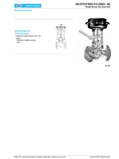
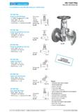
1 Data sheet 700001 englisch (english)Edition 08/19 - Data subject to alteration - Regularly updated data on !ARI-PREDU Pressure regulating valve, straight through with diaphragm actuator DMA Actuator with rolling diaphragmGrey cast iron SG ironCast steel Stainless steelFig. 701 Page 2 ARI-PREDU Pressure reducing valvePressure reducing valve in straightway formDN 15 - 150 Fig. 701 Features: Compact design Construction without pillars Exact and easy adjustment Diameter independent ranges Simple change of spring and actuator 5 exchangeable actuator sizes 3 exchangeable spring sizes Pressure balanced by stainless steel bellow Spindle sealing via stainless steel bellow Tapered seat ring Screwed seat ring Kvs-values reduceable Flow divider for noise reduction (optional) Plug with PTFE soft seal (optional)2 Edition 08/19 - Data subject to alteration - Regularly updated data on !
2 FigureNominal pressureMaterialNominal diameterDownstream-pressure rangesActuator 0,2 - 16 bargDMA 400 DMA 250 DMA 160 DMA 80 DMA 40 +NDN15-150 +NDN15-150 data of the actuator refer to page with Diaphragm-Actuator DMAP ressure regulating valve, straight through with diaphragm actuator DMA Plug DN 15 - 32 Plug DN 40 - 150 Bellows seal DN 15 - 40 Stainless steel - Actuator 3 Edition 08/19 - Data subject to alteration - Regularly updated data on !DN1520253240506580100125150 Kvs-valueKvs-valuestandard(m3/h)3,25812, 520325080125190280reduced(m3/h)0,1 / 0,4 / 1 / 2,50,1 / 0,4 / 1 / 2,5 / 40,1 / 0,4 / 1 / 2,5 / 4 / 6,3----------------Seat- (mm)1822253240506580100125150 Travel(mm)45688101113161922 Max. differential pressure drop(bar)4040252525252020201616 Shutt off classLeakage class I acc. to DIN EN 1349 or DIN EN 60534-4 ( 0,05% from Kvs-value)Face-to-face dimension FTF series 1 according to DIN EN 558 L(mm)130150160180200230290310350400480 Flanges acc.
3 To DIN EN 1092-1/-2 Flange holes / -thickness tolerances acc. to DIN 2533/2544/2545 DPN16(mm)9510511514015016518520022025028 5PN25 / 40(mm)95105115140150165185200235270300 KPN16(mm)657585100110125145160180210240P N25 / 40(mm)657585100110125145160190220250n x dPN16(mm)4 x 144 x 144 x 144 x 184 x 184 x 184 x 188 x 188 x 188 x 188 x 22PN25 / 40(mm)4 x 144 x 144 x 144 x 184 x 184 x 188 x 188 x 188 x 228 x 268 x 26 DimensionsHDMA 400(mm)495495500500540540545585610650690 DMA 250(mm)455455460460500500505545585610650 DMA 160(mm)440440440440480480490530550590630 DMA 80(mm)435435440440480480485530550590630 DMA 40(mm) / / / DMA 400(kg)262728303541487085125158with DMA 250(kg)212223253036436583123156with DMA 160(kg)192021232834416381121154with DMA 80(kg)181920222733406280120153with DMA 40(kg)171819212632396179119152 Downstream-pressure ranges(barg)0,2 - 0,60,5 - 1,20,8 - 2,52 - 54,5 - 108 - 16 Pneumatic Actuator DMA(cm2)
4 DMA 400 DMA 250 DMA 160 DMA 80 DMA 40 Pneumatic Actuator PN-max.(barg)1,62,561020 Spring ranges (Combination: actuator with valve in bar)Pneumatic Actuator (cm )DMA 400 Downstream pressure range (barg)0,2 - 0,60,050,050,050,050,050,060,070,080,080 ,100,15 DMA 2500,5 - 1,20,090,090,060,080,090,090,100,150,100 ,150,23 DMA 1600,8 - 2,50,150,200,150,200,200,250,250,300,350 ,400,50 DMA 802,0 - 5,00,400,450,400,450,350,400,450,500,600 ,750,90 DMA 404,5 - 10,00,550,550,600,650,700,750,800,850,90 1,201,35 DMA 408,0 - 16,00,800,851,001,051,101,251,301,501,75 1,802,00 Pressure reducing valves are proportional regulators with permanent control deviation depending from the construction. The actual control deviation depends on the valve load. (Kv-value / Kvs-value-max) x Proportional range = Actual control deviation The values shown are preliminary values and may vary by the real plantPressure-temperature-ratings Intermediate values for max.
5 Permissible operational pressures can be determined by linear interpolation of the given temperature / pressure to DIN EN 1092-2-60 C to <-10 C*-10 C to 120 C150 C200 C250 C300 C350 CEN-JL1040PN16(bar)--1614,412,811,29,6-- EN-JS1049PN16(bar)on request1615,514,713,912,811,2EN-JS1049PN 25(bar)on request2524,32321,82017,5acc. to manufacturers standard-60 C to <-10 C*-10 C to 120 C150 C200 C250 C300 C350 +NPN25(bar)18,72523,9222017, +NPN40(bar)304038,135322825,7acc. to DIN EN 1092-1-60 C to <-10 C*-10 C to 100 C150 C200 C250 C300 C350 (bar)81615,614,914,113,312, (bar)204039,237,335,433,332,1* Studs and nuts made of A4-70 (at temperatures below -10 C)ARI-PREDU with Diaphragm-Actuator DMA4 Edition 08/19 - Data subject to alteration - Regularly updated data on !ARI-PREDU Application / Sizing ApplicationThe pressure regulating valve is a direct acting proportional regulator, self operated; which regulates a high inlet pressure to a smaller downstream pressure.
6 The downstream pressure is regulated, this means the valve closes when the downstream pressure fields are to regulate fluids of the group II acc. to Pressure Equipment Directive 2014/68/EU, steam, neutral gases, vapours and liquids. With steam and liquids, having temperatures higher than the allowable working temperatures a water seal pot must be installed in the control line (to protect actuator diaphragm) (refer to page 6).Installation in the control line can be seen in the system drawing:Bypass pipeFABA-PlusSAFED ownstream pressure manometerInlet pressure manometerSeparatorFABA-PlusStrainer (Fine screen)Flow indicatorCONA S Ball float steam trapCONA B Bimetallic steam trapFlow indicatorControl lineFABA-PlusWater seal potFABA-PlusPREDU Pressure reducing valveFABA-Plus10 x DN / min. 1m SizingFor the calculation you have the program myValve (Program part Pressure reducing valves ).
7 After giving in the process data, the and size is recommended out of the integrated data bank. The diameter of the piping in front and behind of the pressure regulating valve can also be calculated with the max. allowable flow velocities with necessary downstream pressure gives the needed pressure range. Because the regulation tolerance at the end of the range is smaller, the smaller range must be used, in case of a range overlapping. For example: Downstream pressure 2,4 bar(g), choose actuator range 0,8 - 2,5 bar(g), although 2-5 bar(g) could be safety valve used to secure the downstream pressure must have an adequate distance between set pressure and downstream pressure. The max. possible capacity of the pressure reducing valve is used to select the safety valve at it s set pressure. The max. possible capacity has to be calculated with p1 (= max. possible inlet pressure), p2 (= set pressure of the safety valve) and the Kvs-value of the pressure reducing valve with myValve.
8 With this found capacity you can, with myValve (Program part: Safety valves), select the safety valve, and with the pressure reducing valves and other valves, administer them under a : If not secured that the bypass valve has a larger capacity than the pressure reducing valve, or that it can be open parallel, then the extra capacity must be considered for the safety valve 08/19 - Data subject to alteration - Regularly updated data on !ARI-PREDU Fig. Fig. Fig. Fig. , EN-GJL-250EN-JS1049, EN-GJS-400-18U-LTGP240GH+N, +NGX5 CrNiMoNb19-11-2, seat ring X20Cr13+QT, +QTX6 CrNiMoTi17-12-2, , -A2BA4-704xGasket Pure graphite (CrNi laminated with graphite)5 Bush housingEN-JS1049, EN-GJS-400-18U-LTX6 CrNiMoTi17-12-2, bushX20Cr13+QT, +QTX6 CrNiMoTi17-12-2, Pure graphite (CrNi laminated with graphite)8xBalanced-bellow-unitX6 CrNiMoTi17-12-2, / X5 CrNi18-10, / X20Cr13+QT, +QTX6 CrNiMoTi17-12-2, +QT, +QT (hardened)X6 CrNiMoTi17-12-2, (hardened)10 WasherA2A411 Hexagon screw< DN40: A4-7011 Head DN40: X6 CrNiTi18-10, / X20Cr13+QT, +QT DN50: X6 CrNiTi18-10, >DN50: X6 CrNiTi18-10, /X6 CrNiMoTi17-12-2, Fig.
9 700 closedEN-JS1049, EN-GJS-400-18U-LTGX5 CrNiMoNb19-11-2, nutC35E, -A2BA4-7015xGasket Pure graphite (CrNi laminated with graphite)16xSealing-bellow-unitX6 CrNiMoTi17-12-2, / X5 CrNi18-10, / X20Cr13+QT, +QTX6 CrNiMoTi17-12-2, plateEN-JS1049, EN-GJS-400-18U-LT18 HeadEN-JS1030, EN-GJS-400-1519 Screw joint11 SMn30+C, +C20 Thread pin45H - A2B21 Guide bushPTFE-25%C22 Guide couplingX20Cr13+QT, +QT23 Cylindrical balls102Cr6, wireX12 CrNi17-7, 51 CrV4, plateS235JR, bearing102Cr6, plate11 SMn30+C, +C29 Parallel pinSt30 Slotted - A2B31xP-Actuator diaphragm NBR / nut with sealing nut with / EPDM Spare partsInformation / restriction of technical rules need to be observed!Operating and installation instructions can be downloaded at ARI-Valves of EN-JL1040 are not allowed to be operated in systems acc. to TRD production permission acc. to TRB 801 No.
10 45 is available (acc. to TRB 801 No. 45 EN-JL1040 is not allowed.)The engineer, designing a system or a plant, is responsible for the selection of the correct valve. Resistance and fitness must be verified (contact manufacturer for information, refer to Product overview and Resistance list).6 Edition 08/19 - Data subject to alteration - Regularly updated data on ! Diaphragm-Actuator DMA 400 - DMA 40 Rolling diaphragm Connection through a central thread Spindle connection with a fast coupling Delivered with a flow restrictor and 90 -elbow Material (Diaphragm):EPDM -40 C to +130 CNBR -40 C to +100 CSelection of possible applications: Neutral gases, Vapours and liquids (only fluids of group II acc. to Pressure Equipment Directive 2014/68/EU) Pneumatic ActuatorDMA 400 DMA 250 DMA 160 DMA 80 DMA 40 D(mm)300250210170140H(mm)13590807575 Weight(kg)13,48,15,13,72,9 Water seal pot(for media temperatures higher than the allowed diaphragm temperature) Delivered with a funnelSelection of possible applications: Steam Hot water Neutral liquidsPneumatic ActuatorDMA 400 DMA 250 DMA 160 DMA 80 DMA 40 Size21 D(mm)140102L(mm)11083V(dm3)1,20,6 90 -elbow R1/4" ( ERMETO WE10-LLR) Flow restrictor G1/4" / G1/4"Flow divider for noise reductionPlug with PTFE soft sealing (max.)