Transcription of Fisher L2 Liquid Level Controller - Emerson Electric
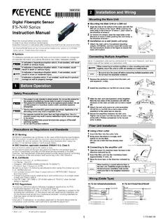
1 L2 Liquid Level of Vertical Horizontal the sensor to the Controller Action or and On/Off Acting Acting Throttling Acting Throttling Acting On/Off andSnap Acting Acting On/Off andSnap Acting of the Controller From the the sensor O the Controller the Controller Supply 1. Fisher L2 Liquid Level ControllerW8418 1 Related of ManualThis instruction manual includes installation, adjustment, maintenance, and parts ordering information for the FisherL2 Liquid Level not install, operate or maintain an L2 Liquid Level Controller without being fully trained andqualified in valve, actuator, and accessory installation, operation, and maintenance. To avoid personalinjury or property damage, it is important to carefully read, understand, and follow all contents of thismanual, including all safety cautions and warnings.
2 If you have any questions about these instructions ,contact your Emerson sales office before ManualD103032X012L2 ControllerJuly 2021 Instruction ManualD103032X012L2 ControllerJuly 20212 Table 1. SpecificationsAvailable ConfigurationsThe Fisher L2 series of controllers include the L2 andL2 Snap modelsController: Snap acting or throttlingSensor: Displacer type Liquid Level sensor formounting to side of tank. Displacer travel istransmitted to Controller by pivotal movement ofdisplacer rodInput SignalType: Liquid Level or Liquid to Liquid interfaceLevel Change Required for Full Change in OutputSignal in Specific Gravity Liquid , with Bar (20 Psig) Supply Pressure, Direct Action, and Standard 48x 305 mm (1 7/8 X 12 Inch) Vertical Displacer withStandard Lever Arm Length:ControlModeMinimum ProportionalBand Level Change, mm(Inches)(1)Maximum ProportionalBand Level Change, mm(Inches)(1)Throttling102 (4)305 (12)On/Off127 (5)305 (12)Snap acting13 ( )20 ( )Minimum Specific Gravity(2)Minimum specific gravity, or specific gravitydifferential for interface applicationsThrottling Controllers: Controllers.
3 Acting Controllers: SignalPneumatic Jon off or Jproportional pressuresignalRanges:Throttling: to bar (3 to 15 psig) or bar (6 to 30 psig)On/Off: 0 (off) or full supply pressure (on)Action: Field reversible between direct (increasinglevel increases output signal) and reverse (increasinglevel decreases output signal)Supply Pressure RequirementsThrottling and On/Off ControllerThrottling: bar for to bar output signal (20psig for 3 to 15 psig output signal) and bar for bar output signal (35 psig for 6 to 30 psigoutput signal)On/Off: Any desired pressure between and bar(20 and 50 psig).Snap Acting Controller : Any desired pressurebetween and bar (20 and 50 psig) direct, bar and bar (20 and 35 psig) reverseDo not use supply pressure below bar (20 psig)Supply MediumAir or natural gas(3)Steady State Air Consumption(4)Throttling Controller : normal m3/hr ( scfh)at bar (20 psig) supply pressureSnap Acting Controller : normal m3/hr ( ) at bar (20 psig) supply pressure or m3/hr ( scfh) at bar (35 psig) supplypressure in tripped condition.
4 Air consumptionincreases during tripSensor to Vessel ConnectionJ2 NPT threaded or JNPS 2 CL150 through 1500slip on flange connection(5) Controller ConnectionsSupply: 1/4 NPT internal located on the bottom of thecaseOutput: 1/4 NPT internal located on the top of thecaseCase Vent: 1/4 NPT internal with vent screenassembly located on the back of the caseStandard Displacer Size48 x 305 mm, 541 cm3 (1 7/8 x 12 inches, 33 in3)Maximum Displacer Insertion Length(6)Standard lever arm length plus one 6 inch extension,horizontal or verticalDisplacer Material and Maximum sensor WorkingPressure(7)PVC Displacer: Consistent with CL1500 pressuretemperature ratings per ASME up tomaximum pressure of 258 bar (3750 psig)For PED (97/23/EC) maximum pressure limited to 200bar (2900 psig)S31603 SST Displacer: CL600 pressure temperatureratings per ASME up to maximum pressure bar (1440 psig)Note: For slip on flange connection, maximum sensorworking pressure must be consistent with the flangeratings-Continued-Instruction ManualD103032X012L2 ControllerJuly 20213 Table 1.
5 Specifications (continued)Displacer Material and sensor TemperatureLimits(7)PVC Displacer: -18 to 71_C (0 to 160_F)S31603 SST Displacer: -40 to 204_C (-40 to 400_F)Operative Ambient Temperature Limits(7) Controller : -29 to 71_C (-20 to 160_F)Standard Supply, and Output Pressure GaugeIndicationsTriple scale gauges in 0 to 60 psig/0 to MPa/0 barHazardous Area ClassificationComplies with the requirements of ATEX Group IICategory 2 Gas and DustEX h IIC Tx GbEX h IIIC Tx DbMaximum surface temperature (Tx) depends onoperating conditionsGas: T6 Dust: T71 Meets Customs Union technical regulation TP TC012/2011 for Groups II/III Category 2 equipmentII Gb c T*XIII Db c T*XDeclaration of SEPF isher Controls International LLC declares thisproduct to be in compliance with Article 4 paragraph3 of the PED Directive 2014/68/EU.
6 It was designedand manufactured in accordance with SoundEngineering Practice (SEP) and cannot bear the CEmarking related to PED , the product may bear the CE marking toindicate compliance with other applicable EuropeanCommunity : Specialized instrument terms are defined in ISA Standard - Process Instrument Any deviation from the standard construction described in the input signal specification above requires special displacer sizing considerations. Contact your Emerson sales office for Depends on float rod/displacer orientation and length. Contact your Emerson sales office before proceeding for further This product can be used with natural gas as the supply medium. 4. Normal m3/hr Normal cubic meters per hour (0_C and bar, absolute) Scfh Standard cubic feet per hour (60_F and psia).
7 5. Converting from a threaded NPT connection to a flange connection is to be done by the end-user. Refer to Converting a Threaded NPT Connection to a Flange Connection instruction ManualSupplement (D103277X012), available at or from your Emerson sales Standard lever arm The pressure and temperature limits in this document and any applicable code limitations should not be rugged L2 Liquid Level controllers use a displacer type sensor (see figure 1) to detect Liquid Level or the interface oftwo liquids of different specific controllers use a single four mode relay to provide the applicable control and action. The device delivers apneumatic output signal to a control/dump otherwise noted, all NACE references are to NACE MR0175 for the Controller and sensor are listed in table ServicesFor information on available courses for L2 Liquid Level Controllers, as well as a variety of other products, contact: Emerson Automation SolutionsEducational Services - RegistrationPhone: 1-641-754-3771 or 1-800-338-8158E-mail.
8 ManualD103032X012L2 ControllerJuly 20214 Installation WARNINGA lways wear protective clothing, gloves, and eyewear when performing any installation operations to avoid avoid personal injury or property damage caused by the sudden release of process fluid, be certain the serviceconditions do not exceed the sensor pressure limits. Use pressure limiting or pressure relieving devices to prevent serviceconditions from exceeding these injury or property damage may result from fire or explosion if natural gas is used as the supply medium andappropriate preventive measures are not taken. Preventive measures may include, but are not limited to, one or more ofthe following: Remote venting of the unit, re evaluating the hazardous area classification, ensuring adequate ventilation,and the removal of any ignition sources.
9 For information on remote venting of this Controller , refer to page with your process or safety engineer for any additional measures that must be taken to protect against installing this into an existing application, also refer to the WARNING at the beginning of the Maintenance section of thisinstruction not use sealing tape on pneumatic connections. This instrument contains small passages that may become obstructedby detached sealing tape. Thread sealant paste should be used to seal and lubricate pneumatic threaded the L2 Level Controller is installed on a vessel that is to be shipped to a different location ( skid mounted units), removethe displacer and displacer rod extensions before shipment. Failure to do so could result in damage to the displacer rod dueto vibration and impact loading during shipment.
10 After the vessel is installed at its final location, reassemble the displacerand displacer rod Be sure there are no obstructions inside the tank that will interfere with displacer installation or Provide the appropriate connection in the tank wall to match the sensor connection. Locate the tank wallconnection such that the displacer will be at the desired control a Vertical DisplacerRefer to figure 7 for part Thread jam nut (key 68) all the way onto the threaded portion of the universal joint assembly (key 69).2. Thread the displacer (key 81) all the way onto the threaded portion of the universal joint Tighten the jam nut (key 63) against the displacer (key 81).Instruction ManualD103032X012L2 ControllerJuly 20215 Attaching a Horizontal DisplacerRefer to figure 7 for part Thread the displacer (key 81) all the way onto the displacer rod (key 64) or extension (key 82).