Transcription of Fixed frequency VIPer plus family - st.com
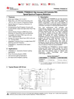
1 This is information on a product in full production. June 2014 DocID15232 Rev 71/30 VIPER16 Fixed frequency VIPer plus familyDatasheet - production dataFigure 1. Typical application Features 800 V avalanche rugged power section PWM operation with frequency jittering for low EMI Operating frequency : 60 kHz for L type 115 kHz for H type No need of auxiliary winding for low power application Standby power < 30 mW at 230 VAC Limiting current with adjustable set point On-board soft-start Safe auto-restart after a fault condition Hysteretic thermal shutdown Application Replacement of capacitive power supply Auxiliary power supply for appliances, Power metering LED drivers DescriptionThe device is an off-line converter with an 800 V avalanche ruggedness power section, a PWM controller, user defined overcurrent limit.
2 Protection against feedback network disconnection, hysteretic thermal protection, soft start up and safe auto restart after any fault condition. It is able to power itself directly from the rectified mains, eliminating the need for an auxiliary bias winding. Advance frequency jittering reduces EMI filter cost. Burst mode operation and the devices very low consumption both help to meet the standard set by energy saving regulations.',3 62 QDUURZT able 1. Device summaryOrder codesPackagePackaging VIPER16 LNDIP-7 TubeVIPER16 HNVIPER16 HDSO16 narrowTubeVIPER16 HDTRTape and reelVIPER16 LDTubeVIPER16 LDTRTape and Rev 7 Contents1 Block diagram.
3 42 Typical power .. 43 Pin settings .. 54 Electrical data .. ratings .. data .. characteristics .. 85 Typical electrical characteristics .. 116 Typical circuit .. 147 Power section .. 168 High voltage current generator .. 169 Oscillator .. 1710 Soft start-up .. 1711 Adjustable current limit set point .. 1712FB pin and COMP pin .. 1813 Burst mode .. 1914 Automatic auto restart after overload or short-circuit .. 2015 Open loop failure protection .. 21 DocID15232 Rev 73/30 VIPER16 Contents3016 Layout guidelines and design recommendations.
4 2317 Package mechanical data .. 2518 Revision history .. 29 Block diagramVIPER164/30 DocID15232 Rev 71 Block diagram2 Typical power Figure 2. Block diagram Table 2. Typical powerPart number230 VAC85-265 VACA dapter(1)1. Typical continuous power in non ventilated enclosed adapter measured at 50 C frame(2)2. Maximum practical continuous power in an open frame design at 50 C ambient, with adequate heat (1)Open frame(2)VIPER169 W10 W5 W6 W DocID15232 Rev 75/30 VIPER16 Pin settings303 Pin settingsFigure 3.
5 Connection diagram (top view)Note:The copper area for heat dissipation has to be designed under the DRAIN pins. $0 Y 1 & 1 $ '5$,1'5$,1'5$,1'5$,1'5$,1'5$,1 Table 3. Pin descriptionPin to the source of the internal power MOSFET and controller ground available for user. This pin is mechanically connected to the controller die pad of the frame. In order to improve the noise immunity, is highly recommended connect it to GND (pin 1-2).25 VDDS upply voltage of the control section. This pin provides the charging current of the external pin allows setting the drain current limitation to a lower value respect to IDlim, which is the default one.
6 The limit can be reduced by connecting an external resistor between this pin and GND. In case of high electrical noise, a capacitor could be connected between this pin and GND, the capacitor value must be lower than 470 nF in order to not impact the functionality of the pin. The pin can be left open if default drain current limitation, IDlim, is input of the internal trans conductance error amplifier. Connecting the converter output to this pin through a single resistor results in an output voltage equal to the error amplifier reference voltage (see VFB_REF on Tab l e 8). An external resistors divider is required for higher output settingsVIPER166/30 DocID15232 Rev 758 COMPO utput of the internal trans conductance error amplifier.
7 The compensation network have to be placed between this pin and GND to achieve stability and good dynamic performance of the voltage control loop. The pin is used also to directly control the PWM with an optocoupler. The linear voltage range extends from VCOMPL to VCOMPH (Ta bl e 8).7,813-16 DRAINHigh voltage drain pin. The built-in high voltage switched start-up bias current is drawn from this pin too. Pins connected to the metal frame to facilitate heat 3. Pin description (continued)Pin Rev 77/30 VIPER16 Electrical data304 Electrical Maximum Thermal dataTable 4.
8 Absolute maximum ratingsSymbolPin (DIP-7)ParameterValueUnitMinMaxVDRAIN7, 8 Drain-to-source (ground) voltage 800 VEAV7, 8 Repetitive avalanche energy (limited by TJ = 150 C)2mJIAR7, 8 Repetitive avalanche current (limited by TJ = 150 C)1 AIDRAIN7, 8 Pulse drain current (limited by TJ = 150 C) pin pin pin limitedVIDD2 Input current 20mAPTOTP ower dissipation at TA < 40 C (DIP-7)1 WPower dissipation at TA < 60 C (SO16N)1 WTJO perating junction temperature range-40150 CTSTGS torage temperature-55150 CESD(HBM) 1 to 8 Human body model4kVESD(CDM)1 to 8 Charge device 5.
9 Thermal data SymbolParameterMax valueSO16 NMax valueDIP-7 UnitRthJPThermal resistance junction pin (Dissipated power = 1 W)3540 C/WRthJAThermal resistance junction ambient (Dissipated power = 1 W)90110 C/WRthJAThermal resistance junction ambient (1)(Dissipated power = 1 W)1. When mounted on a standard single side FR4 board with 100 mm2 ( sq in) of Cu (35 m thick)8090 C/WElectrical dataVIPER168/30 DocID15232 Rev Electrical characteristics (TJ = -25 to 125 C, VDD = 14 V (a); unless otherwise specified) a. Adjust VDD above VDDon start-up threshold before setting to 14 VTable 6.
10 Power section SymbolParameterTest conditionMin Typ Max UnitVBVDSSB reak-down voltageIDRAIN = 1 mA, VCOMP = GND, TJ = 25 C800 VRDS(on)Drain-source on state resistance IDRAIN = A, TJ = 25 C2024 IDRAIN = A, TJ = 125 C4048 COSSE ffective (energy related) output capacitance VDRAIN = 0 to 640 V10pFIOFFOFF state drain currentVDRAIN = 640 VVFB = GND60 AVDRAIN = 800 VVFB = GND75 ATable 7. Supply section SymbolParameterTest conditionMin Typ Max UnitVoltageVDRAIN_STARTD rain-source start voltage405060 VIDDch1 Start up charging currentVDRAIN = 100 V to 640 V, VDD = 4 current during operationVDRAIN = 100 V to 640 V, VDD = 9 V falling edge-7-14mAVDDO perating voltage clamp voltageIDD = 15 start up threshold121314 VVDDCSonVDD on internal high voltage current generator under voltage shutdown threshold789 VDocID15232 Rev 79/30 VIPER16 Electrical data30 CurrentIDD0 Operating supply current, not switchingFOSC = 0 kHz.