Transcription of Flow control valves type QV-06 - atos.com
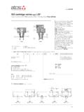
1 QV-06 /1 QV-06 /6 QV-06 /11 QV-06 /16 QV-06 /24 1,5 6 11 16 24 5024 3 3 5 6,5 8 24 250 Flow control valves type QV-06 pressure compensated, two way, ISO 4401 size 06QV are flow control valves with pressure compensator : the controlled flow rate is independent of pressure variations.
2 They are usually supplied with a built-in check valve to allow the free flow in the opposite direction. The flow is regulated by turning a gradua-te micrometer knob . Clockwise rotation increases the flow regulation. Optional versions with locking key on the adjustment knob are available on request. valves designed to operate in hydraulic systems with hydraulic mineral oil or synthetic fluid having similar lubricating characteristics. Size: 06 - ISO 4401 Max flow: 24 l/min Max pressure: 250 bar Pressure compensated flow control valve1C210 Maximum adjustable flow rate: 1 = 1,5 l/min 11 = 11 l/min24 = 24 l/min 6 = 6 l/min 16 = 16 l/min Options: K = with lock key for the setting knob V = without by-pass check valveSize.
3 06 MODEL CODE2 HYDRAULIC CHARACTERISTICSV alve model Max regulated flow [I/min] Min regulated flow [cm3/min] Max flow B A through check valve [l/min] Regulating p [bar] Max flow on port A [l/min] Max pressure [bar]Hydraulic symbolswith check valve (standard)without check valve (option /V)QV-06QV-06/*/KSeries numberQV066///-K**3 MAIN CHARACTERISTICS, SEALS AND FLUIDS - for other fluids not included in below table, consult our technical officeMineral oilsHydraulic fluidNBR, FKM, HNBR FKM NBR, HNBRDIN 51524 ISO 12922 HL, HLP, HLPD, HVLP, HVLPD HFDU, HFDR HFCS uitable seals typeClassificationRef.
4 StandardFlame resistant without waterFlame resistant with water NBR seals (standard) = -20 C +80 C, with HFC hydraulic fluids = -20 C +50 C Seals, recommended fluid temperature FKM seals (/PE option) = -20 C +80 C HNBR seals (/BT option) = -40 C +60 C, with HFC hydraulic fluids = -40 C +50 C Recommended viscosity 15 100 mm2/s - max allowed range 2,8 500 mm2/s Assembly position Any position Max fluid contamination level ISO4406 class 20/18/15 NAS1638 class 9, see also filter section at or KTF catalog Ambient temperature Standard = -30 C +70 C /PE option = -20 C +70 C /BT option = -40 C +70 CSeals material, see section 3.
5 - = NBR PE = FKM BT = HNBRT able C210-8/ECompliance RoHS Directive 2011/65/EU as last update by 2015/65/EU REACH Regulation (EC) n 1907/2006QV-064 DIAGRAMS based on mineral oil ISO VG 46 at 50 C6 MODULAR PLATES TYPE Regulation diagram 1 = QV-06 /1 2 = QV-06 /6 3 = QV-06 /11 4 = QV-06 /16 5 = QV-06 /24 Q/ p diagram through the check valve for free flow B A 6 = QV-06 /* Setting [notch on the knob]Flow [l/min]Flow [l/min]Differential pressure [bar]The modular plates type BHQ allow the assembling of valves type QV-06 in a modular stack with other components having ISO 4401 size 06 mounting surface.
6 See below for model code and functional sketches; see section 5 for dimensions and example of also version for phosphate ester (add /PE at the end of the model code).7 MOUNTING PLATES TYPE BAValveBA-202/Q BA-204/Q BA-302/QPorts A, B, P, T underneath; Ports P, T underneath; Ports A, B on lateral side Ports A, B, P, T underneath; G 3/8 1,2 G 3/8 25,5 1,2 G 1/2 30 1,8 Subplate modelPorts locationPorts A, B, P, T Counterbore [mm] A, B, P, TMass [Kg]03/20546321 BHQ-011 BHQ-023 BHQ-013 BHQ-024 BHQ-014 BHQ-012 BHQ-016 BHQ-0225 DIMENSIONS [mm]Option /KMass: 1,2 KgISO 4401: 2005 Mounting surface: 4401-03-02-0-05 (see note 1) Fastening bolts: 4 socket head screws M5x70 class Tightening torque = 8 Nm Seals: 2 OR 117 Diameter of ports A, B.
7 = 7 mm = Flow control valve type QV-06 Note that the valve(s) is (are) mounted: on side port A for BHQ-011, BHQ-013, BHQ-016 and BHQ-023 on side port B for BHQ-014 and BHQ-024 on both sides for BHQ-012 and BHQ-022 = Modular plate type BHQ, see section 6 = Closing element. This element can be on side port A or side port B depending on models. It is not present on BHQ-011, BHQ-016, BHQ-012 and BHQ-022 = Directional valve type DH* (ISO 4401 size 06)ASSEMBLY IN MODULAR STACK see section 6note 1: the manifold interface has to be provided only of the A and B ports.
8 The valve cannot be installed on manifolds with ISO 4401-AB-03 interface with P and T view from X