Transcription of FLR12 Installation Instructions - Forward Lift
1 October 2009 by Forward Lift. All rights reserved. IN60008 Rev. - 10/19/2009 FLR12 Installation InstructionsFour Post Surface Mounted LiftCapacity 12,000 lbs. (6,000 lbs. per axle)2 Dimension at highest position minus other position = shim thickness required3. Estimating Column Shim requirements: In the following section, the terms highest and lowest refer to elevation of Mark locations where lift columns will be positioned in Place target on floor at column positions (NOT on column base plates) and record readings, Fig. Find the highest of the four locations. Find the difference between the reading at each of the remaining three columns and the highest reading.
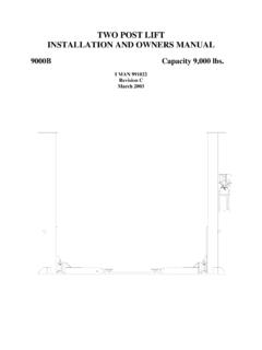
2 D. The difference is the estimated amount of shim thickness needed at each : Maximum shim thickness is 1/2" per column using shims and anchors provided with lift. Shim thickness of 2" is possible by using optional shim kit #FC5393. Contact your authorized Forward Parts Distributor for ordering SHIM ESTIMATESNote: Target is positioned on floor at planned col-umn positions (NOT on column base plates).Read and understand these Instructions completely before proceeding with lift Lift Location: Use architects plan when available to locate lift. Fig. 1 shows dimensions of a typical bay layout. Lift floor area should be DO NOT install on asphalt or other similar unstable surface.
3 Columns are supported only by anchors in Ceiling or overhead clearance must be 80" plus height of tall-est 1 Fig. 2 Installation INSTRUCTIONREQUIRED CLEARANCESC APPROACHL Right RunwayLeftRunway12' 0" Min. To Door orNearest Obstruction14' 0" Min. ToNearest Obstruction8' 0" Min. ToNearestObstruction8' 0" Min. ToNearestObstruction4'-7" Min. ToNearestObstruction35. Runway Attachment:With the openings in the yoke tube side lined up with the left runway ends, align the two (2) holes in the top of the front yoke tube with the slots in the runway end plates. Bolt runway to the yoke using four 1/2" x 1-1/4" hex flange bolts, Fig. 4. 4. Runway and Yoke Tube Assembly: A.
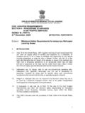
4 Determine direction of approach in bay. B. Position left runway in bay with hydraulic cylinder hose connection to front of bay. Cables and sheaves are pre-assembled in runway. Runway needs to be up off floor so shipping restraints can be removed from cable ends, air and hydraulic lines, and cylinder rod. Pull cable ends, air, and hydraulic lines out for assembly. Make sure cables are in proper sheave grooves, Fig. Position front and rear yokes at respective ends of runway, Fig. 1. The opening in the side of the yokes should be lined up with the cable sheaves in the runway ends. Feed cable ends through yoke openings, Fig. 4 . Do not assemble sheaves in yoke ends at this time.
5 IMPORTANT Be sure cables are not crossed inside yoke. Right Front Cable (#1)Right Rear Cable (#3)REARLeft Front Cable (#2)FRONTR ight Front Cable (#1)Left Rear Cable (#4)Left Front Cable (#2) CABLES IN PROPER SHEAVE GROOVES FEED CABLE ENDS THROUGH YOKE OPENINGSF ront YokeCableRight RunwayFront YokeCableRunway SheaveLeft Runway1/2"-13 x 1-1/4" hex flange Whiz-Lock1/2"-13 x 1-1/4" hex flange Whiz-LockFront Wheel StopFig. 3 Fig. 44 FRL BracketPower UnitColumn#10-24NC Nylon Lock NutJam NutJam NutLatch BarAdjustment NutNutWasherThreaded CableThreaded StudFRL#10-24NC x 3/4" SHCS6. Column and Yoke Assembly: A. Place the power unit column at the left rear corner of the lift.
6 The hydraulic cylinder connection in the left runway should be visible from this corner. Position remaining three columns. Adjustment NutJam NutLatch BarLATCH BAR IN COLUMNATTACH SLIDERSE. Raise latch bar above sliders and move column toward yoke until the sliders contact the back of the column. Lower the latch bar into the sliders. Tighten latch bar jam nut against column top plate. Run latch bar adjustment nut down and tighten. The latch bar should engage the sliders for at least 1" when the lift is completely lowered. Repeat this procedure for each yoke end and Install yoke end sheaves and plastic spacers, Fig. 8. A plastic spacer is placed on each side of the sheave, inset Fig.
7 8. Note: Failure to install plastic spacer will result in premature failure and void Be sure cable is located in the sheave Retain with sheave pin and 5/16" hex head machine bolt. Attach each cable to column top plate with spacer, nut, and jam nut, Fig. 8. Install rubber sheave guard on each yoke end, Fig. 8. Roping diagram shows a view of completed roping, Fig. 9. D. Start yoke end into the column, allowing slider bolt holes to stay exposed, Then bolt sliders onto each side of the yoke end with 5/16"- 18NC bolts provided. When both sliders are attached, push column toward yoke end until sliders touch latch bar. B. Thread the jam nut down the threaded stud as far as possible.
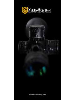
8 Stick rubber bumper to bottom of latch bar, see Fig. 7. Place the latch bar in the back of the column, Fig. 5a. The latch bar is offset from the center line of the threaded stud (inset Fig. 6). The latch bar should be oriented toward the back of the column from center line of the threaded stud, Fig 6. C. Place FRL Bracket on top of power unit column. Guide the threaded stud through the hole in the column top plate and bracket, Fig. 5b. Then thread the adjustment nut down the threaded stud until the nut and top plate are flush, Fig 5b. Repeat for other columns. LATCH BAR OFFSETFig. 5bFig. 7 Fig. 6 Pull Latch Bar up above BarYokeColumnSlider5/16"-18NC HHCS x 3/4" 5aLatch BarLATCH BAR CROSS SECTIONThis side faces outThreaded StudATTACH FRL51234 LEFT FRONT #2 LEFT REAR #4 CLOSED YOKECABLE ROUTINGRIGHT FRONT #1 PULL BAR #5 RIGHT REAR #32341 Nut5/16" Hex Hd.
9 Bolt1/4" Plain Washer1/4"-20 x 1/2" lg. Type T Hex. Hd. Tapping ScrewPlastic GuardSheaveSheave PinPlastic Spac-ersLatch Bar Adjustment StudJam NutTOP VIEW (top removed)Plastic SpacersSheaveYoke Side PlateYoke EndColumnSHEAVE INSTALLATIONW asherFig. 8 Fig. 9 Run Cables Through Retainer Before Attaching Them to Pull BarCABLE ROPINGDo Not Cross Cables at Either EndCable Retainer Not Shown to Clarify Cable Roping Illustra-tion67. Column Anchoring:A. Concrete shall have a compression strength of at least 3,000 PSI and a typical slab thickness of 5-1/2 to 6 and should sustain 2000# anchor load. B. Keep columns square to center line of lift. Check lift location in the bay.
10 Check dimensions side-to- side, front-to-rear, and diagonally. Diagonals must be equal to within 1/4", Fig. Move column towards yoke until the sliders contact the back of column, center yoke in column, Fig. CROSS SECTIONYokeSliderLatch BarFig. 10 Fig. 11 Width and length measurements are made from column sides, NOT column base plate. Diagonals are mea-sured from out side corner of RunwayRight RunwayDiagonalswithin 1/4"116" LIFT DIMENSIONS219-13/16" Ref. EL2195-13/16" Ref. L7A)Concrete Thickness & Hole Depth 4-1/4" (108mm)B)Edge Distance 4-3/4" (121mm)C)Hole Spacing 6-1/2" (165mm)ABCCBCCD. Place shims (estimated in Step 3) under each column. Drill four 5/8" diameter holes through concrete floor using base holes as guide.