Example: biology
Ford AOD Hi-Tech Kickdown Kit Installation Instructions
Step 10:On the passenger side of the transmission near the tail housing, you will find three test ports. The T.V. test port is the one in the middle. Fig. 10 Remove the block off plug from the T.V. test port, and connect an oil pressure gauge with hose (not included) using a …
Tags:
Information
Domain:
Source:
Link to this page:
Documents from same domain
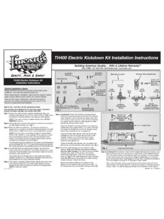
TH400 Electric Kickdown Kit Installation Instructions
www.lokar.comStep 5:(Continued)Position the kickdown mounting bracket behind the carburetor bracket so that the 5/16" diameter holes at the top of both brackets are aligned, the small

700-R4, 4L60, and 4L60E Automatic Case Mount Shifter ...
www.lokar.comFig. 4 If you have a 4 wheel drive application that will not accept the rear mounting bracket, start the 5/16"-24 x 5/8" tension set screws into the tension set screw holes at the front and in the center of the shifter main plate. Set the mounting bracket assembly into place on top of the transmission. Fig. 4

Ford C4 and C6 Hi-Tech Kickdown Kit Installation Instructions
www.lokar.comFord C4 and C6 Hi-Tech Kickdown Kit Installation Instructions Step 5: Con( inued) t Attach the kickdown mounting bracket to the Cable Bracket using the supplied #8-32 x 1/2" button head bolt and nylock nut through the small 3/16" diameter center holes in both brackets, but do
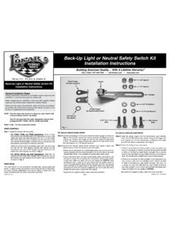
Back-Up Light or Neutral Safety Switch Kit Installation ...
www.lokar.comNOTE: This Kit offers the choice of a Back-Up Light Switch OR a Neutral Safety Switch, Not Both! 5/16"-18 x 1-1/4" This Kit will work with the Lokar Adjustable Column Shift Linkage EXCEPT TH400, 700-R4, 4L60E and 4L80E. Refer to Fig. 1 for the component names. Switch Installation: Step 1: Install the bracket with the switch:

Throttle Cable Installation Instructions - Lokar
www.lokar.com(NOTE: If a Lokar Kickdown Kit is being used, install the kickdown mounting bracket onto the back side of the Cable Mounting Bracket first.) Then, position the rear adjuster nut so that the threaded part of the throttle cable adjuster is approximately centered in the Cable Mounting Bracket. Reinstall the front adjuster nut. Fig. 3
TH400 Electric Kickdown Kit Installation Instructions
www.lokar.comStep 5:The kickdown mounting bracket mounts onto the back side of the Lokar Cable Bracket. The throttle cable adjuster will pass through the top hole in both the new kickdown mounting bracket AND the Cable Bracket. TOLL FREE 1-877-469-7440 • tech@lokar.com • www.lokar.com ® TH400 Electric Kickdown Kit Installation Instructions
Related documents

IMCA Racing, 1800 West D Street, P.O. Box 921, Vinton, IA ...
www.imca.cominner wheel wells may be removed. OEM or aluminum aftermarket replacement trunk lid allowed. Quarter panels and trunk lid must slope down minimum 1 inch toward tailpiece. Rear edge of trunk lid may be trimmed and rear tail light support removed only if aftermarket tailpiece is used. Hood and trunk must be securely fastened.

Wisconsin ATV/UTV Law Changes Effective March 4, 2020
dnr.wi.govAftermarket seating does not comply with the new law change. Lighted Headlamp Display Requirements . Previously ATVs and UTVs were required to have a lighted headlamp & tail lamp during hours of darkness or during daylight hours when within a highway. ATVs and UTVs are now required to have a lighted headlamp & tail lamp at all times during ...

Harness/Schematic Location Information 1B-3 1B
westernstar.blob.core.windows.netQuestion: I have installed aftermarket LED tail lamps to my vehicle but they are not working properly. Answer: The WST electrical turn signal system requires a minimum amperage load from the tail light system. When LED lights are used a resistor needs to be added to increase the load to an acceptable level.

INSTRUCTIONS 910-64017 - Speedway Motors
static.speedwaymotors.comAlso, whenever using AFTERMARKET or SPECIALTYequipment, always use the diagrams PROVIDED WITHthat equipment. This WORKBOOK is designed for both our labeled and color-coded harnesses. Whenever ... We suggest you start with the TAIL SECTIONand end with the DASH SECTION.
2022 USRA FACTORY STOCK RULES
usraracing.comNov 18, 2020 · 1.2 Stock appearing aftermarket plastic nose piece may be drilled for air but may not be extended with any type of material. Tail pieces with no holes are permitted. 1.3 Rear of car must be sealed off so that fuel cell is not exposed. 1.4 Spoilers (even if factory equipped), wings, skirts, valiances, air scoops, hood scoops or anything that

RST90Y RS Venture Owners Manual
www.yamahamotorsports.comto test the products that these aftermarket companies produce. Therefore, Yamaha can neither endorse nor recommend the use of accessories not sold by Yamaha or modifica-tions not specifically recommended by ... 14.Tail/brake lights 15.Slide rail …
2022 Rule Book Amendments 12-20-2021
www.nhraracer.comAftermarket full-floating axle assembly mandatory. Aftermarket axles with minimum 5/8-inch-diameter studs and axle-retention device mandatory. Maximum (numeric) rear-end gear ratio 4.57- to-1 for roots supercharged and turbocharged entries. Centrifugally supercharged maximum (numeric) rear-end gear ratio 4.29.

Wiring Kit Instructions - American Autowire
www.americanautowire.comdistributor, to the Negative side of the coil, or a tach connection in an aftermarket ignition moduleO such as an MSD module. See the installation instructions for the type of distributor you are using for specific connection requirements. 5. Select the pink Ignition Feed wire (3A). This is the 12 volt power source for the distributor.