Transcription of G5V-1 - Omron
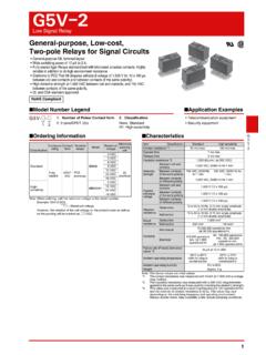
1 1G5V-1G5V-1 Low Signal RelayUltra-miniature, Highly Sensitive SPDT Relay for Signal Circuits Ultra-miniature at 10 mm (L W H). Wide switching power of 1 mA to 1 A. High sensitivity: 150 mW nominal coil power consumption. Fully-sealed construction offering environment resistance. Conforms to FCC Part 68 requirements for coil to contacts. (1,500 V, 10 160 s) Models for ambient temperatures up to 90 C added to series. Model Number Legend Ordering Information Note: When ordering, add the rated coil voltage to the model number. Example: G5V-1 DC3 However, the notation of the coil voltage on the product case as well as on the packing will be marked as @@ VDC.
2 RatingsRoHS CompliantClassificationEnclosure ratingContact formTerminalShapeModelRated coil voltageMinimum packing unitStandardFully sealedSPDT(1c)PCB terminalsG5V-13 VDC25 pcs/tube5 VDC6 VDC9 VDC12 VDC24 VDCG5V-1-T90G5V-1-T905 VDC12 VDC24 VDC Application Examples Telecommunication equipment Audio-visual products Security equipment Building automation equipment Standard Model SpecificationsContact type: Single crossbar (Au-alloy + Ag)Enclosure rating: Plastic sealedTerminal shape: PCB terminalsG5V-@-@ 121. Number of Poles/Contact Form1: 1-pole/SPDT (1c)2. ClassificationNone: Standard (Ambient operating temperature 70 C max.)
3 T90: Ambient operating temperature 90 C coil voltage CoilG5V-1 (Standard) G5V-1 -T90 Note 1. The rated current and coil resistance are measured at a coil temperature of 23 C with a toleranceof 10%. 2. The operating characteristics are measured at a coil temperature of 23 C. 3. The maximum voltage is the highest voltage that can be imposed on the relay coil. 4. G5V-1 -2 types with a must operate voltage of 70% max. are available as special series voltageRated current (mA)Coil resistance ( )Must operate voltage (V)Must release voltage (V)Max. voltage(V)Power consumption(mW)% of rated voltage3 VDC506080% at 23 CApprox.
4 1505 VDC301676 VDC252409 ,840 Rated voltageRated current (mA)Coil resistance ( )Must operate voltage (V)Must release voltage (V)Max. voltage(V)Power consumption(mW)% of rated voltage5 VDC3016770% at 23 CApprox. 15012 ,840 ContactsLoadItemResistive loadContact typeSingle crossbarContact materialAu-alloy + AgRated A at 125 VAC; 1 A at 24 VDCR ated carry current2 AMax. switching voltage125 VAC, 60 VDCMax. switching current1 A2G5V-1 Low Signal RelayG5V-1 CharacteristicsContact resistance *1100 m : The values here are initial values.* with 10 mA at 1 VDC with a voltage drop method.* with a 500 VDC megohmmeter between coil and contacts and a 250 VDC megohmmeter between contacts with the same polarity applied to the same parts as those used for checking the dielectric strength.
5 * value was measured at a switching frequency of 120 operations/min and the criterion of contact resistance is 100 .This value may vary depending on the switching frequency and operating environment. Always double-check relay suitability under actual operating time 5 ms max. Release time5 ms max. Insulation resistance *21,000 M min. (at 500 VDC between coil and contacts, at 250 VDC between contacts of same polarity.)Dielectric strengthBetween coil and contacts1,000 VAC, 50/60 Hz for 1 minBetween contacts of the same polarity400 VAC, 50/60 Hz for 1 minVibration resistanceDestruction10 to 55 to 10 Hz, mm single amplitude ( mm double amplitude)Malfunction10 to 55 to 10 Hz, mm single amplitude ( mm double amplitude)Shock resistanceDestruction1,000 m/s2 Malfunction100 m/s2 DurabilityMechanical5,000,000 operations min.
6 (at 36,000 operations/hr)Electrical100,000 operations min. (under rated load, at 1,800 operations/hr)Failure rate (P level) (reference value) *31 mA at 5 VDCA mbient operating temperature-40 C to 70 C (Standard), -40 C to 90 C ( G5V-1 -T90)(with no icing or condensation)Ambient operating humidity5% to 85%WeightApprox. 2 g3G5V-1 Low Signal RelayG5V-1 Engineering Data* tests were conducted at an ambient temperature of 23 C.* contact resistance data are periodically measured reference values and are not values from each monitoring operation. Contact resistance values will vary according to the switching frequency and operating environment, so be sure to check operation under the actual operating conditions before use.
7 High-frequency Characteristics Test Conditions Maximum Switching Capacity Durability Ambient Temperature vs. Maximum Coil VoltageNote: The maximum coil voltage refers to the maximum value in a varying range of operating power voltage, not a continuous voltage. Ambient Temperature vs. Must Operate or Must Release VoltageG5V-1G5V-1-T90 Shock MalfunctionTest conditions: Shock is applied in X, Y, and Z directions three times each with and without energizing the Relays to check the number of contact malfunctions. Dial Pulse Test *1 Contact Reliability Test *1, *2 Switching current (A) 30 50 70 100 300 500 Switching voltage (V)DC resistive loadAC resistiveload 125 VAC resistive load24 VDC resistive loadDurability (x104 operations)50030010070503010750 current (A)Maximum coil voltage (%)250200150100500 Ambient temperature ( C) 40 200204060807090 100 StandardG5V-1-T90On the basis of rated voltage (%)
8 100 80 60 40 20 0 -60 -40 -20 0 20 40 60 80 100 Ambient temperature ( C)Sample: G5V-1 Number of Relays: 10 pcs max. max. X X min. min. Must operate voltage Must release voltage On the basis of rated voltage (%)Ambient temperature ( C)Sample: G5V-1 -T90 Number of Relays: 10 pcsMust operate voltageMust release voltage100806040200 60 40 20 0 20 40 60 80 X 'YY'XX'2004006008008006004002001,0001,00 01,0001,0001,0001,000 Shock directionUnit: m/s2 Sample: G5V-1 12 VDCN umber of Relays: 10 pcsYY'XX'De- energizedEnergizedZZ'0 50 100 500 1,000 5,000 10,000 50,000 Rotation ( 103 turns)80706050403020101,0005003001005030 10On the basis of rated voltage (%)Contact resistance (m )Must operate voltageContact resistance Must release voltageSample: G5V-1 12 VDCN umber of Relays: 6 pcsTest conditions: Contact load WJ-139 (with arc-killer)Switching frequency.
9 ContactNC contact1,00050040030020010050403020100 5 10 50 100 500 1,000 Operating frequency ( 104 operations)Contact resistance (m )Sample: G5V-1 12 VDCN umber of Relays: 10 pcsTest conditions: resistive load at 5 VDC 1 mASwitching frequency: 7,200 operations/hNO contactNC which were not being measured were terminated with 50 .Measuring impedance: 50 HR 8502 ATransmissionreflectiontest-setTerminato r50 G5V-1HR 8502 ANetwork analyzer HP 8501 AStoragenormalizerRFRABNote: The high-frequency characteristics data were measured using a dedicated circuit board and actual values will vary depending on the usage conditions.
10 Check the characteristics of the actual equipment being Signal RelayG5V-1 Dimensions Approved StandardsUL recognized: (File No. E41515)CSA certified: (File No. LR31928) Precautions Please refer to PCB Relays Common Precautions for correct use. Long-term Continuously ON ContactsUsing the Relay in a circuit where the Relay will be ON continuously for long periods (without switching) can lead to unstable contacts, because the heat generated by the coil itself will affect the insulation, causing a film to develop on the contact surfaces. Be sure to use a fail-safe circuit design that provides protection against contact failure or coil burnout.