Transcription of G6E - Omron
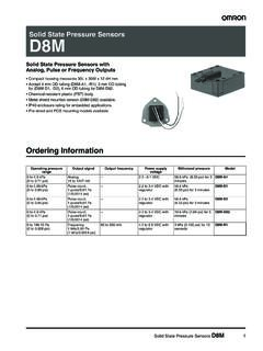
1 G6E. Low Signal Relay Subminiature, Sensitive SPDT. Signal Switching Relay High sensitivity: 98-mW (Rated power consumption: 200mW) pickup coil power. Impulse withstand voltage of 1,500V (10 160 s) meets FCC requirements. Stick packing employed in consideration of supporting automatic implementation. Plastic-sealed model that allows automatic soldering. New series of ultrasonically cleanable models is available. Standard model conforms to UL/CSA standards. RoHS Compliant Model Number Legend Application Examples G6E-@ -@ @@ @ @ -@ -@ Telecommunication equipment G. Office automation machines 6. 1 2 3 4 5 6 7 8. Industrial equipment E. 1. Relay Function 4. Enclosure Rating 7. Approved Standards Security equipment None: Single-side stable 4: Fully sealed US: UL, CSA. U : Single-winding latching K : Double-winding latching 5. Terminals Shape ( UL: FILE CSA: FILE ).
2 P: PCB terminals 2. Number of poles/ 8. Special Function 6. Classification None : Standard Contact Form None : Standard U : For ultrasonically 1: 1-pole/SPDT (1c). L : Low sensitivity coil cleanable 3. Contact Type (400 mW). 3: Bifurcated crossbar Ag (Au-Alloy) contact Ordering Information Standard Models (UL, CSA certified). Relay Function Single-side stable Single-winding latching Double-winding latching Classification Standard Low-sensitivity Standard Standard Low-sensitivity Minimum packing Rated coil Rated coil Rated coil Rated coil Rated coil unit Contact form Model Model Model Model Model voltage voltage voltage voltage voltage 5 VDC 5 VDC 5 VDC 5 VDC 5 VDC. 6 VDC 6 VDC 6 VDC 6 VDC 6 VDC. G6E G6EU G6EK G6EK. G6E 9 VDC 9 VDC 9 VDC 9 VDC . SPDT (1c) -134PL-US -134P-US -134P-US -134PL-US 25 pcs/tube -134P-US 12 VDC 12 VDC 12 VDC 12 VDC 12 VDC.
3 24 VDC 24 VDC 24 VDC 24 VDC 24 VDC. 48 VDC . Models for Ultrasonically Cleanable Relay Function Single-side stable Single-winding latching Double-winding latching Classification Standard Low-sensitivity Standard Standard Minimum packing Rated coil Rated coil Rated coil Rated coil unit Contact form Model Model Model Model voltage voltage voltage voltage 5 VDC 5 VDC 5 VDC 5 VDC. 6 VDC . G6E G6EU G6EK. G6E 9 VDC . SPDT (1c) -134PL-US-U -134P-US-U -134P-US-U 25 pcs/tube -134P-US-U 12 VDC 12 VDC 12 VDC 12 VDC. 24 VDC 24 VDC 24 VDC. 48 VDC . Note: When ordering, add the rated coil voltage to the model number. Example: G6E-134P-US DC5. Rated coil voltage However, the notation of the coil voltage on the product case as well as on the packing will be marked as @@ VDC. 1. G6E Low Signal Relay Ratings Coil: Single-side Stable Must operate Must release Max.
4 Rated Coil voltage voltage voltage Power Classification Rated voltage current resistance (V) (V) (V) consumption (mA) ( ) (mW). % of rated voltage 5 VDC 125. 6 VDC 180. 190%. 9 VDC 405 Approx. 200. (at 23 C). Standard 12 VDC 720 70% max. 10% min. 24 VDC 2,880. 170%. 48 VDC 5,760 Approx. 400. (at 23 C). 5 VDC 63. 6 VDC 90. 170%. Low-sensitivity 9 VDC 203 70% max. 10% min. Approx. 400. (at 23 C). 12 VDC 360. 24 VDC 1,440. Coil: Single-winding latching Must set voltage Must reset voltage Max. voltage Rated current Coil resistance Power consumption Contact type Rated voltage (V) (V) (V). (mA) ( ). % of rated voltage Set coil (mW) Reset coil (mW). 5 VDC 125. G 6 VDC 180. Bifurcated 190%. 6 crossbar 9 VDC 405 70% max. 70% max. (at 23 C). Approx. 200 Approx. 200. E 12 VDC 720. 24 VDC 2,880. Coil: Double-winding latching Must set Must reset Max. Rated current (mA) Coil resistance ( ) voltage voltage voltage Power consumption Classification Rated voltage (V) (V) (V).
5 Set coil Reset coil Set coil Reset coil Set coil Reset coil % of rated voltage (mW) (mW). 5 VDC 125 125. 6 VDC 180 180. 190%. Standard 9 VDC 405 405 70% max. 70% max. Approx. 200 Approx. 200. (at 23 C). 12 VDC 720 720. 24 VDC 2,880 2,880. 5 VDC 63 63. 6 VDC 90 90. 170%. Low-sensitivity 9 VDC 203 203 70% max. 70% max. Approx. 400 Approx. 400. (at 23 C). 12 VDC 360 360. 24 VDC 1,440 1,440. Note 1. The rated current and coil resistance are measured at a coil temperature of 23 C with a tolerance of 10%. 2. Operating characteristics are measured at a coil temperature of 23 C. 3. The maximum voltage is the highest voltage that can be imposed on the relay coil. 4. Refer to the engineering data for relations between the ambient temperature and maximum coil voltage. Contacts Load Inductive load Resistive load Item (cos = ; L/R = 7 ms). Contact type Bifurcated crossbar Contact material Ag (Au-Alloy).
6 A at 125 VAC; A at 125 VAC;. Rated load 2 A at 30 VDC 1 A at 30 VDC. Rated carry current 3A. Max. switching voltage 250 VAC, 220 VDC. Max. switching current 3A. 2. G6E Low Signal Relay Characteristics (Including Models for Ultrasonically Cleanable). Item Relay Function Single-side Stable Single-winding Latching Double-winding Latching Contact resistance *1 50 m max. Operate (set) time 5 ms max. Release (reset) time 5 ms max. Min. set pulse width 15 ms Min. reset pulse width 15 ms Insulation resistance *2 1,000 M min. (at 500 VDC). Impulse withstand Between coil and contacts 2,500 V (10 160 s) (conforms to FCC part 68). voltage Between contacts of same polarity 1,500 V (10 160 s) (conforms to FCC part 68). Between coil and contacts 1,500 VAC, 50/60 Hz for 1 min Dielectric strength Between contacts of same polarity 1,000 VAC, 50/60 Hz for 1 min vibration Destruction 10 to 55 to 10 Hz, mm single amplitude (5 mm double amplitude).
7 Resistance Malfunction 10 to 55 to 10 Hz, mm single amplitude ( mm double amplitude). Destruction 1,000 m/s2. Shock resistance Malfunction 300 m/s2. Mechanical 100,000,000 operations min. (at 36,000 operations/hr). 100,000 operations min. ( A at 125 VAC resistive load; A at 125 VAC inductive load). (at 1,800 operations/hr). Durability Electrical 500,000 operations min. (2 A at 30 VDC resistive load; 1 A at 30 VDC inductive load). (at 1,800 operations/hr). 200,000 operations min. (3 A at 30 VDC resistive load) (at 1,800 operations/hr). Failure rate (P level) (reference value) *3 10 A at 10 mVDC. Ambient operating temperature -40 C to 70 C (with no icing or condenstion). Ambient operating humidity 5% to 85%. Weight Approx. g Note: The values here are initial values. G. *1. The contact resistance was measured with 1 A at 5 VDC using a voltage-drop method.
8 6. *2. The insulation resistance was measured with a 500 VDC Megger Tester applied to the same parts as those used for checking the dielectric strength. E. *3. This value was measured at a switching frequency of 120 operations/min and the criterion of contact resistance is 50 . This value may vary depending on the switching frequency and operating environment. Always double-check relay suitability under actual operating conditions. Engineering Data Maximum Switching Power Durability Ambient Temperature vs. Maximum Coil Voltage 10 10,000 280. Durability (x104 operations). Switching current (A). Maximum coil voltage (%). 5 5,000 260. DC resistive load G6E-134P-US. 3 3,000. 240 G6EK-134P-US. 2 G6EU-134P-US. 30 VDC inductive load AC resistive load 1,000 (L/R = 7 ms) 220. 1. 500 200. DC inductive load (L/R = 7 ms) 300 30 VDC resistive load 180. AC inductive load G6E-134PL-US.
9 100 125 VAC 160. (cos = ) G6EK-134PL-US. resistive G6EU-134P-US. 50 140. load Only at 48 VDC. 30. 125 VAC 120. inductive load 10 (cos = ) 100. 5 0. 0 3 5 10 20 30 50 100 300 500 1,000 0 1 2 3 4 -50 -40 -20 0 20 40 60 80 100. Switching voltage (V) Switching current (A) Ambient temperature ( C). Note: The maximum coil voltage refers to the maximum value in a varying range of operating power voltage, not a continuous voltage. Ambient Temperature vs. Must Shock Malfunction Operate or Must Release Voltage G6E-134P-US G6EK-134P-US. On the basis of rated voltage (%). 100 De-energized Y Reset Y. 1,000 1,000. Coil is applied with Energized Set 130% of rated voltage 80. Coil is applied with X Z X Z. 100% of rated voltage 1,000 1,000 1,000 1,000. 600. 60 Hot start voltage 500 Shock direction Shock direction (max. value) X X'. X X'. Voltage not applied to Cold start voltage Y Y.
10 The coil and contacts (max. value) 0 Z 0 Z. Release voltage at 700. 40 600 Z' Z'. hot start (min. value) Y' Y'. Release voltage at 1,000 1,000. Z' X' Z' X'. Coil terminal Contact terminal Coil terminal Contact terminal cold start (min. value). Coil is applied with 1,000 1,000. 20 100% of rated voltage 1,000 1,000. Unit: m/s2 Y' Unit: m/s2 Y'. 0 Voltage not applied to the coil and contacts Sample: G6E-134P-US 24 VDC Sample: G6EK-134P-US 12 VDC. -40 -20 0 20 40 60 80 100 120. Number of Relays: 10 pcs Number of Relays: 20 pcs Ambient temperature ( C). Test Conditions: Shock is applied in X, Y, and Z directions three times each with and without energizing the Relays to check the number of contact malfunction. 3. G6E Low Signal Relay Contact Reliability Test *1, *2 Contact Reliability Test (70 C) *1, *2 Mutual Magnetic Interference G6E-134P-US G6E-134P-US G6E-134P-US.