Transcription of GBU6005 - GBU610
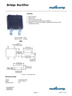
1 E3DS21226 Rev. 7 - 21 of Diodes IncorporatedGBU6005 - glass passivated bridge RECTIFIERF eaturesMaximum Ratings and Electrical Characteristics@ TA= 25 C unless otherwise specifiedMechanical DataSingle phase, 60Hz, resistive or inductive capacitive load, derate current by 20%.Notes:1. Unit mounted on 50mm x 50mm x copper plate Non-repetitive, for t > and < Measured at and applied reverse voltage of RoHS revision glass and High Temperature Solder Exemptions Applied, seeEU Directive Annex Notes 5 and 7. Case: GBU Case Material: Molded Plastic. UL FlammabilityClassification Rating 94V-0 Terminals: Plated Leads. Solderable per MIL-STD-202,Method 208 Lead Free Plating (Tin Finish) Polarity: Marked on Body Mounting: Through Hole for #6 Screw Mounting Torque: Inch-pounds Maximum Ordering Information: See Last Page Marking: Date Code and Type Number Weight: grams (approximate)CharacteristicSymbolGBU6005 GBU601 GBU602 GBU604 GBU606 GBU608 GBU610 UnitPeak Repetitive Reverse VoltageWorking Peak Reverse VoltageDC Blocking VoltageVRRMVRWMVR501002004006008001000 VRMS Reverse VoltageVR(RMS)3570140280420560700 VAverage Forward Rectified Current (Note 1) @ TC= 100 CI(AV) Peak Forward Surge Current half sine-wave superimposed on rated loadIFSM175 AForward Voltage (per element)@ IF= Reverse Current@ TC= 25 Cat Rated DC Blocking Voltage@ TC= 125 Rating for Fusing (t < ) (Note 2)I2t127A2sTypical Total Capacitance per Element (Note 3)CT100pFTypical Thermal Resistance Junction to Case (Note 1)
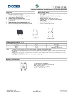
2 C/WOperating and Storage Temperature RangeTj,TSTG-55 to +150 X 45 Dimensions in mm-~~+ABKDEFGHJMNPLC glass passivated Die Construction High Case Dielectric Strength of 1500 VRMS Low Reverse Leakage Current Surge Overload Rating to 175A Peak Ideal for Printed Circuit Board Applications UL Listed Under Recognized ComponentIndex, File Number E94661 Lead Free Finish, RoHS Compliant (Note 4)Notes: 5. For packaging details, visit our website at Rev. 7 - 22 of , INSTANTANEOUS FORWARD CURRENT (A)FV , INSTANTANEOUS FORWARD VOLTAGE (V) Typical Forward Characteristics, per elementFT=25Cj , PEAK FORWARD SURGE CURRENT (A)FSMNUMBER OF CYCLES AT 60 HzFig. 3 Maximum Non-Repetitive Surge CurrentSingle half-sine-wave00246255075100125150I, AVERAGE FORWARD RECTIFIED CURRENT (A)(AV)T , CASE TEMPERATURE ( C)Fig. 1 Forward Current DeratingCurveC Resistive orInductive load351 With heatsinkWithout heatsink101001110100C , TOTAL CAPACITANCE (pF)TV , REVERSE VOLTAGE (V) Typical Total Capacitance, per elementRf = Ordering InformationDevicePackagingShippingGBU600 5 GBU20/TubeGBU601 GBU20/TubeGBU602 GBU20/TubeGBU604 GBU20/TubeGBU606 GBU20/TubeGBU608 GBU20/TubeGBU610 GBU20/Tube(Note 5)DS21226 Rev.
3 7 - 23 of NOTICELIFE SUPPORTD iodes Incorporated and its subsidiaries reserve the right to make modifications, enhancements, improvements, corrections or other changes without furthernotice to any product herein. Diodes Incorporated does not assume any liability arising out of the application or use of any product described herein;neitherdoes it convey any license under its patent rights, nor the rights of others. The user of products in such applications shall assume all risks of such useand willagree to hold Diodes Incorporated and all the companies whose products are represented on our website, harmless against all Incorporated products are not authorized for use as critical components in life support devices or systems without the expressed written approval of thePresident of Diodes Incorporated.