Transcription of General AXF Specifications - yokogawa.com
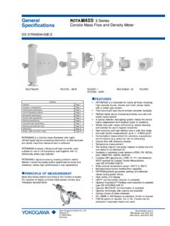
1 GeneralSpecifications<<Contents>> <<Index>>Yokogawa Electric Corporation2-9-32, Nakacho, Musashino-shi, Tokyo, 180-8750 JapanTel.: +81-422-52-4443 Fax.: +81-422-52-2018GS 01E20D01-01 EGS 01E20D01-01E Copyright June 2003(YK)19th Edition May 2016(KP)AXFM agnetic FlowmeterIntegral Flowmeter/Remote FlowtubeIntegral FlowmeterRemote FlowtubeThe AXF magnetic flowmeter series are sophisticatedproducts with outstanding reliability and ease ofoperation, developed on the basis of decades of field-proven combination of a replaceable electrode and thediagnostic to defect adhesion level on the electrodesdramatically improves AXF employs the fluid noise free Dual FrequencyExcitation Method and the newly added Enhanced DualFrequency Excitation Method as an option for moredifficult applications to ensure greater stability and.
2 The Dual Frequency Excitation Method isYo kogawa s unique communication type is also to GS 01E20F02-01E for FOUNDATIONTM fieldbuscommunication type and GS 01E20F12-01E forPROFIBUS PA communication type regarding the itemsmarked with . FEATURES User-oriented FunctionalityFluid Adhesion Level DiagnosisBy constantly monitoring the level of insulatingsubstance on the electrodes, it is possible to determinewhen maintenance is the utilization of an optional replaceable electrode,the electrodes can be easily removed from the flowmeterand Electrical Connection DirectionThe converter or the terminal box can be rotatedarbitrarily to change the directions of electricalconnection on the and Versatile IndicationsThe LCD indicator employs a large, backlit full dot-matrix, that can facilitate various to three lines are available.
3 When there is an alarmcondition, a full description of the countermeasure isindicated. Easy Setup Parameters The most frequently used parameters are arranged in agroup at the infra-red switches enable the users to setparameters without opening the cover. Expansion of Product LineupImproved Accuracy SpecificationThe standard accuracy is of reading. Alsoavailable is an optional high accuracy calibration rated of Small Size Flange TypeThe flange type is now available from a mm Sanitary ConnectionsA variety of sanitary connections are available, such asTri-Clamp, ISO, DIN and SMS. Enhanced Performance and SpecificationsEnhanced Dual Frequency Excitation MethodThe Enhanced Dual Frequency Excitation Method canbe optionally difficult applications such as for high concentrationslurries or low conductivity fluid, extremely stablemeasurements can be Minimum ConductivityThe newly designed AXF converter permits themeasurement of fluids with conductivity as low as 1 Pulse Output The pulse rate now goes up to 10,000 pps (pulse/second) for use with high speed applications such as inshort time batch Input/Ouput Function for Integral Flowmeter Integral type is also equipped with versatile P.
4 1 Standard Specifications P. 2 Hazardous Area Classification Performance Operating Conditions for Installation rminal Configuration and Terminal Wiring and Suffix Code Specifications for Flowtubes Dimensions Data Information <<Contents>> <<Index>>GS 01E20D01-01 EAll Rights Reserved. Copyright 2003, Yokogawa Electric CorporationMay 31, 2016-00 STANDARD Specifications Converter (Integral flowmeter)The contents of (*1) and (*2) described in the converterspecifications are follows.*1: Select two points from: one pulse output, one alarmoutput, one status input, or two status outputs.*2: For models without an indicator, the configuration tool(Such as HHT (handheld terminal) or FieldMateTMetc.) is necessary to set Method: Standard dual frequency excitation:Size to 400 mm ( to 16 in.)
5 Enhanced dual frequency excitation:Size 25 to 200 mm ( to in.)(Optional code HF1 or HF2)Input Signal (*1) :One Status Input: Dry contactLoad Resistance: 200 or less (ON), 100 k or more(OFF)Output Signals : One Current Output: 4 to 20 mA DC (load resistance:750 maximum, including cable resistance) One Pulse Output (*1):Transistor contact output (open collector)Contact capacity: 30 V DC (OFF), 200 mA (ON)Output rate: to 10,000 pps (pulse/second) One Alarm Output (*1):Transistor contact output (open collector)Contact capacity: 30 V DC (OFF), 200 mA (ON) Two Status Outputs (*1):Transistor contact output (open collector)Contact capacity: 30 V DC (OFF), 200 mA (ON)Communication Signals :BRAIN or HART communication signal(Superimposed on the 4 to 20 mA DC signal)Distance from Power Line: 15 cm (6 in.)
6 Or more(Parallel wiring should be avoided.)BRAIN:Communication Distance:Up to km ( miles), when polyethylene insulatedPVC-sheathed cables (CEV cables) are distance varies depending on the typeof cable and wiring Resistance:250 to 450 (including cable resistance)Load Capacitance: F or lessLoad Inductance: mH or lessInput Impedance of Communicating Device:10 k or more (at kHz)HART:Load Resistance:250 to 600 (including cable resistance)Note: HART is a registered trademark of the Security During Power Failure:Data (parameters, totalizer value, etc.) storage byEEPROM. No back-up battery (*2):Full dot-matrix LCD (32 132 pixels)Lightning Protector:The lightning protector is built into the current output andpulse/alarm/status input and output terminals. Whenoptional code A is selected, the lightning protector isbuilt into the power : General -purpose Use/Sanitary Type/TIIS Flameprooftype:IP66/IP67 Explosion proof type except TIIS:In case of explosion proof type except TIIS, refer todescription of "Enclosure" in "HAZARDOUS AREACLASSIFICATION".
7 Coating:Case and Cover: Corrosion-resistant coatingCoating Color; Mint green coating (Munsell or its equivalent)Converter Material:Case and Cover : Aluminum alloyMounting/Shapes (Integral Flowmeter): Electrical Connection:ANSI 1/2 NPT femaleISO M20 femaleJIS G1/2 female Direction of Electrical Connection: The direction can bechanged even after delivery. Terminal Connection: M4 size screw terminalGrounding:Grounding resistance 100 or lessWhen optional code A is selected, grounding resis-tance 10 or less shall be applied.*In case of explosion proof type except TIIS, follow thedomestic electrical requirements as regulated in eachcountry.*In case of TIIS Flameproof type, refer to description of HAZARDOUS AREA CLASSIFICATION .Functions How to Set Parameters (*2):The indicator s LCD and three infra-red switchesenable users to set parameters without opening thecase cover.
8 Parameters can also be set with theconfiguration tool (Such as HHT (handheld terminal)or FieldMate, etc.). The language for the HHT isEnglish Languages (*2):Users can choose a language from among English,Japanese, German, French, Italian, and Flow Rate/Totalized Value DisplayFunctions (for models with an indicator) (*2):The full dot-matrix LCD enables user selections ofdisplays from one line to three lines for: Instantaneous flow rate Instantaneous flow rate (%) Instantaneous flow rate (bar graph) Current output value (mA) Totalized forward-direction flow rate Totalized reverse-direction flow rate Totalized differential flow rate Tag No. Results of electrode adhesion diagnostics Communication type3<<Contents>> <<Index>>All Rights Reserved. Copyright 2003, Yokogawa Electric CorporationGS 01E20D01-01E May 31, 2016-00 Totalizer Display Function (*2):The flow rate is counted one pulse at a time according tothe setting of totalization pulse weights.
9 For forward andreverse flow measurement functions, the totalizedvalues of the flow direction (forward or reverse) and theflow direction are displayed on the indicator togetherwith the units. The difference of totalized values betweenthe forward and reverse flow rate can be for the reverse flow rate is carried out onlywhen Forward and reverse flow measurement func-tions is Time Constant (*2):Time constant can be set from second to (63% response). The default is 3 Setting Function (*2):Span flows can be set in units such as volume flow rate,mass flow rate, time, or flow rate value. The velocity unitcan also be Flow Rate Unit: kcf, cf, mcf, Mgal (US), kgal (US),gal (US), mgal (US), kbbl (US)*, bbl (US)*,mbbl (US)*, bbl (US)*, Ml (megaliter), m3,kl (kiloliter), l (liter), cm3 Mass Flow Rate Unit (Density must be set.)
10 :klb (US), lb (US), t (ton), kg, gVelocity Unit: ft, m (meter)Time Unit: s (sec), min, h (hour), d (day)* US oil or US Beer can be Output (*1)(*2):Scaled pulse can be output by setting a pulse Width: Duty 50% or fixed pulse width ( , , , 1, 20, 33, 50, 100 ms) can be Rate: to 10,000 pps (pulse/second)Multi-range Function (*1)(*2): Range switching via status inputStatus input enables the switching of up to two ranges. Automatic range switchingWhen the flow rate exceeds 100 % of the range,transition to the next range (up to four ranges) iscarried out automatically. Range switching can beconfirmed by status outputs and and Reverse Flow Measurement Functions (*1)(*2):Flows in both forward and reverse directions can bemeasured. The reverse flow measurement can beconfirmed by status output and Switch (*1)(*2):The status output is carried out when a totalized valuebecomes equal to or greater than the set Totalization (*1)(*2):The parameter setting or status input enables a totalizedvalue to be preset to a setting value or Signal Lock (*1)(*2):Status input forcibly fixes the instantaneous flow ratedisplay, current output, pulse output, and flow ratetotalization to 0%.