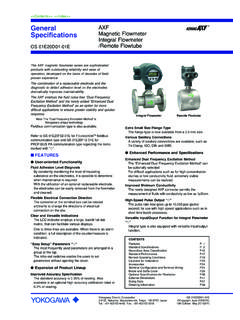
Transcription of General AXR 6SHFL¿FDWLRQV Two-wire Magnetic Flowmeter ...
1 GeneralSpecifications<<Contents>> <<Index>>AXRTwo- wire Magnetic FlowmeterIntegral FlowmeterYokogawa Electric Corporation2-9-32, Nakacho, Musashino-shi, Tokyo, 180-8750 JapanTel.: +81-422-52-4443 Fax.: +81-422-52-2018GS 01E30D01-01 ENGS 01E30D01-01EN Copyright Aug. 2009 (KP)5th Edition Mar. 2016 (KP)n General DESCRIPTIONThe ADMAG AXR Two-wire Magnetic Flowmeter can be installed in the Two-wire system without any AC power source, thus drastically reducing the initial instrumen-tation ADMAG AXR is the world s first Two-wire Magnetic Flowmeter which employs the fluid noise free Dual Frequency Excitation Method, achieving excellent stability for the AXF four- wire Magnetic Flowmeter series, the ADMAG AXR has user-friendly functions such as a full dot-matrix LCD indicator, electrode adhesion level diagnosis function, and a multi-lingual display.
2 The magnet switches can be used for checking and setting parameters without opening the case : The Dual Frequency Excitation Method is Yokogawa s unique FEATURESl High Performance and Excellent FunctionalityDual Frequency Excitation MethodThe Dual Frequency Excitation Method combines two strengths: stability in flow measurement due to low frequency excitation and high noise resistance due to high frequency excitation. Therefore, the method is strong against fluctuations of fluid condition and is ideal for stable Accuracy The ADMAG AXR performs of rate under nor-mal flowrate Noise ResistanceThe ADMAG AXR offers electric noise resistance compared with the four- wire Magnetic ReliabilityThe ADMAG AXR complies with SIL2 for safety requirement.
3 The ADMAG AXR has SIL2 capability for single Flowmeter use and SIL3 capability for dual Flowmeter Reducing the Instrumentation CostReducing the Wiring CostThe Two-wire system reduces the wiring cost Connection with the DCSAC power sources are not necessary. The ADMAG AXR can be connected with almost all distributors, signal conditioner cards, and input SavingCompared with four- wire Magnetic flowmeters, the ADMAG AXR can drastically decrease power User-friendly FunctionalityEnhanced Diagnostic FunctionBy checking the level of the insulating substance on the electrodes, it is possible to determine when main-tenance is of mean flow measurement during a given period, etc. can be checked by using and Versatile IndicationsThe full dot-matrix LCD indicator facilitates various displays such as one to three lines and multi-lingual an alarm condition, a full description of the coun-termeasure is SettingMagnet switches and push switches are switches enable parameters to be set without opening the case cover in the hazardous Output SignalsIn addition to the current output, one output can be selected among pulse, alarm, and status.
4 Vari-ous functions such as multiple-range, forward and reverse flow measurement, and flow rate upper/lower limit alarm are achieved. The pulse output is a high speed of 10,000 pps (pulses per second).CONTENTSG eneral description, Features Specifications Area Classification Performance Operating Conditions for Installation Configuration and Terminal Wiring Example and Suffix Code Specifications Dimensions Data Information [Style: S2]2<<Contents>> <<Index>>All Rights Reserved. Copyright 2009, Yokogawa Electric CorporationGS 01E30D01-01 ENMar. 28, 2016-00n STANDARD SPECIFICATIONSl ConverterThe contents of (*1) and (*2) described in the converter specifications are follows.
5 *1: One output can be selected from pulse, alarm, or status through the parameter setting.*2: For models without an indicator, the con-figuration tool (Such as handheld terminal or FieldMate, etc.) is necessary to set or change Method: Dual frequency excitation: Size 25 to 200 mm (1 to 8 in.)Output Signals:Current output and digital output can be carried out WIRING EXAMPLE . Current output: 4 to 20 mA DC, Two-wire system Output range: to mA ( to ) Digital output (*1): Transistor contact output, open collector Contact rating: 30 V DC, 120 mA DC Low level: 0 to 2 V DC (Read Figure 1)HIGH levelLOW level0 V0 to 2 1 High and Low levels (transistor contact output)Current Output Status at System Alarms (Burnout)Up-scale: 110%, mA DC or more (standard)Down-scale: 5%, mA DC or lessSupply to 42 V DC for General -purpose use and explo-sion proof to 32 V DC for lightning protector (optional code A)Note 1: Supply voltage means the voltage necessary to pro-vide between the power terminals of the Magnetic 2.
6 Connecting with the commercial AC power supply will damage the Flowmeter . Be sure to use the DC power supply in the predetermined 3: The ADMAG AXR can be connected with almost all distributors, signal conditioner cards, and I/O modules except certain the following table for Yokogawa s devices, choose an appropriate connecting device and the corresponding length of devices other than those in the table, decide on the connection by reading the supply voltage specifi-cations and the description in WIRING EXAMPLE .Connecting deviceMaximum length of cable (rough guideline)Name Model Cable with cross section of 2 mm2 Cable with cross section of mm2 Signal Conditioner CardEA1 EA22 km2 kmI/O ModuleAAM11 AAM11B2 km2 kmAnalog I/O Module (for FIO)AAI1432 km2 kmAAI141 AAI841 AAI135 AAI835 Not applicableNot applicableAnalog I/O Module (for Prosafe-RS) km km DistributorSDBT SDBS2 km2 kmJUXTAVJA1 VJA4 VJA72 km2 kmCommunication Requirement:BRAINC ommunication Signal:BRAIN communication signal (superimposed on 4 to 20 mA DC signals)Conditions of Communication Line:Supply Voltage: to 42 V DCLoad Resistance: 250 to 600 (including cable resistance)Read Figure Distance.
7 Up to a distance of 2 km when a CEV cable is usedRead WIRING EXAMPLE .Load Capacitance: F or lessLoad Inductance: mH or lessDistance from other Power Line: 15 cm (6 in.) or more (Avoid parallel wiring.)Input Impedance of Communicating Device: 10 k or more at supply voltage E (V DC)R= Communication Range (BRAIN or HART)External Load Resistance R ( )Figure 2 Relationship Between Power Supply Voltage And External Load ResistanceHARTC ommunication Signal:HART communication signal (superimposed on 4 to 20 mA DC signals)Note: HART is a registered trademark of the FieldComm of Communication Line:Supply Voltage: to 42 V DC3<<Contents>> <<Index>>All Rights Reserved. Copyright 2009, Yokogawa Electric CorporationGS 01E30D01-01 ENMar.
8 28, 2016-00 Load Resistance: 250 to 600 (including cable resistance)Read Figure Protocol Revision:HART protocol revision can be selected from 5 or 7 when ordering. ( -J only)The protocol revision can be changed by user HART protocol revision at the time of shipment is shown by the last number at the serial number column of the name : Protocol revision supported by HART configuration tool must be the same or higher than that of of HART 5/ HART 7 Output Signal Code-E-JOrdering Information Specify 5 Specify 7 HART Protocol RevisionHART 5 HART 7 Selec-tion guideRequire-ment for HART 7 function-alityNOYESBe sure to confirm the protocol revision of the HART configura-tion tool shown in Note condi-tionsNot avail-able to switch to HART 7 protocol after to switch to HART 7 proto-col after delivery by to switch to HART 5 proto-col after delivery by 1 Note 2 Note 2 Note 1: "-E" is HART5 exclusive model and will be terminated.
9 "-J" is recommended for HART 2: HART protocol revision for the device and HART configuration toolHART 7 communication is supported by Field-Mate or revision supported by HART configuration tool57 AXR, HART 5 AvailableAvailableAXR, HART 7 Not availableAvailableIndicator (*2):Full dot-matrix LCD (128 x 64 pixels)Operational switch: 4 magnet switches (including push switches)Lightning Protector:When optional code A is selected, the lightning pro-tector is built into the power supply and digital output : General -purpose Use/TIIS Flameproof type:IP66/IP67, Type 4 XExplosion proof type except for TIIS:In the case of explosion proof type except TIIS, read description of Enclosure in HAZARDOUS AREA CLASSIFICATION.
10 Converter Coating:Case and Cover: Corrosion-resistant coatingCoating Color: Mint-green paint (Munsell BG or its equivalent)Converter Material:Case and Cover: Aluminum alloyMounting/Shapes: Electrical Connection: ANSI 1/2 NPT female ISO M20 x female JIS G1/2 female Direction of Electrical Connection: The direction can be changed even after delivery. Terminal Connection: M4 size screw terminalGrounding:Grounding resistance of 100 or less is the optional code A is selected, grounding resistance of 10 or less shall be required.* In case of TIIS explosion proof type, read descrip-tion of HAZARDOUS AREA CLASSIFICATION.* For an explosion proof type except for TIIS, follow the domestic electrical requirements in each to Set Parameters (*2):Both of four push buttons and magnet switches can be used for setting.


