Transcription of GENERAL INSTALLATION, OPERATION, …
1 GENERAL installation , OPERATION, maintenance AND TROUBLESHOOTINGMANUALFORIMO PUMP TWO SCREW PRODUCTSWARNINGThis manual, and the specific INSTRUCTION MANUAL, should beread thoroughly prior to pump installation , operation, maintenanceor No. GTS/2300 CA-1 Rev. 0 July 1998 TMThis manual now isidentified as part THIS ENTIRE PAGE BEFORE PROCEEDINGFOR THE SAFETY OF PERSONNEL AND TO PREVENT DAMAGE TO THE EQUIP-MENT, THE FOLLOWING NOMENCLATURE HAS BEEN USED IN THIS MANUAL:D A N G E RFailure to observe the precautions noted in this box can result in severebodily injury or loss of A R N I N GFailure to observe the precautions noted in this box can cause injury topersonnel by accidental contact with the equipment or liquids.
2 Protectionshould be provided by the user to prevent accidental to observe the precautions noted in this box can cause damage orfailure of the AND TABLE OF CONTENTS .. AA - GENERAL .. 1B - TRANSPORTATION AND STORAGE .. 1C - DESCRIPTION OF THE PUMP .. 1D - installation /ASSEMBLY .. 1E - STARTUP, OPERATION AND SHUTDOWN .. 8F - maintenance .. 12G - FIELD AND FACTORY 16H - troubleshooting .. 17 Non-compliance of safety instructionsidentified by the following symbol couldaffect safety for persons:Safety instructionswhere electrical safetyis involved are identi-fied by:Safety instructions which shall be con-sidered for reasons of safe operationof the pump and/or protection of thepump itself are marked by the sign:ATTENTIONAAPPLICATIONS MANUAL FOR IMO PUMP TWO SCREW PRODUCTSA.
3 GENERALThe instructions found herein cover the GENERAL installation , operation, maintenance and trouble-shooting of subject equipment:NOTE:Individual contracts may have specific provisions that vary from this manual. Should anyquestions arise which may not be answered by these instructions, refer to the specific pumpinstruction manual provided with your order. For further detailed information and technicalassistance to questions not answered by this manual, please refer to Imo Pump, Technical/Customer Service Department, at 704 289-6511 for GTS pumps. For 2200/2300 Seriespumps refer to Imo Pump-Warren, Technical/Customer Service Department at manual cannot possibly cover every situation connected with the installation , operation, mainte-nance and troubleshooting of the equipment supplied.
4 Every effort was made to prepare the text ofthe manual so that engineering and design data was transformed into easily understood Pump must assume the personnel assigned to operate and maintain the supplied equipment andapply this instruction manual have sufficient technical knowledge and experience to use sound safetyand operational practices which may not be otherwise covered by this applications where equipment furnished by Imo Pump is to become part of a process or othermachinery, these instructions should be thoroughly reviewed to determine proper fit of the equipmentinto overall plant operational installation , operation, and maintenance instructions are not correctly and strictly fol-lowed and obser ved, injury to personnel or serious damage to pump could result.
5 ImoPump cannot accept responsibility for unsatisfactory performance or damage resultingfrom failure to comply with TRANSPORT AND STORAGEA lways protect the pump against entry of water or other contaminants. Store the pump in a clean, dryand indoor environment. Pumps are delivered with internals oiled (unless specified otherwise by thecustomer order) and protective covers in or over all openings. These covers should remain in placeduring the mounting and alignment procedures. The covers must be removed just prior to attachingsystem piping to pump. If pumps are to be stored in other than a clean, warm, dry environment, or ifthey are to be stored for more than six months, contact Imo Pump for appropriate storage DESCRIPTION OF THE PUMPSee specific pump instruction manual provided with your installation /ASSEMBLYWARNINGOn critical or dangerous equipment, provide safety and emergency systems to protectpersonnel and property from injury due to pump malfunction.
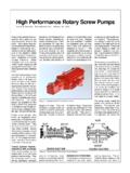
6 If pumped liquids are flam-mable, toxic, corrosive, explosive or otherwise hazardous, provide for safety in the event ofleakage or malfunction. BEFORE working on equipment, make sure all power to equip-ment is disconnected and TOOLSThe procedures described in this manual require common mechanics hand tools, dial indicatorsfor alignment and suitable lifting devices such as slings, straps, spreader bars, LIFTING OF PUMP AND PUMP/DRIVER ASSEMBLIESAll pumps and pump/driver assemblies should be lifted with appropriate devices securely at-tached to the whole unit. Ensure unit s center-of-gravity is located between lifting points. SeeFigure 1. This will avoid tipping of pump or pump/driver assembly. Spreader bars should beused as necessary to insure load is properly distributed and lifting straps do not damage pumps and pump/driver assemblies have designated lifting points that are shown on theiroutline a vertical pump/driver using straps or hooks attached to the pump or pump-to-driver bracket may be dangerous since the center-of-gravity of the assembly may be higherthan the points of attachment.
7 Take precautions to prevent slippage of slings and use properly rated lifting 1 Lifting Pumps and Pump/Driver installation OF PUMP ASSEMBLYTo insure adequate flow of liquid to pump s inlet port, place pump near liquid source and prefer-ably place pump centerline below liquid surface. Use short, straight inlet dry, clean, well-lit and well-ventilated site should be selected for installing the pump open space should be provided around pump to permit routine visual inspection,service, maintenance , or replacement. For installation and servicing of large pump units, ampleoverhead clearance should be provided to allow for lifting device FOUNDATIONS AND BASEPLATESF oundations and baseplates must be designed and installed so pump and driver alignment canbe maintained at all times.
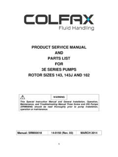
8 Be sure baseplates are level and rest on smooth flat surfaces. Smallpumps may be mounted on baseplates or directly to existing floors that meet the criteria offoundations. Larger pumps and/or drivers must be mounted to baseplates and foundations. It isrecommended that pumps and their drivers be mounted on common baseplates. Use shims orblocks near foundation bolts to avoid springing unit when bolts are 90 Mi n 60 Max 90 Mi n 60 Max 90 MOUNTING OF FOOT MOUNTED PUMPS AND DRIVERSSome pumps are shipped on baseplates without drivers. For these units, install and tighteneach coupling half on driver and pump shafts. Place driver on baseplate and set proper dis-tance between shafts and coupling hubs (see Figure 2).
9 Locate driver so pump and drivershafts are in axial alignment. See Section on pump feet individually to ensure that they do not move more than in. ( mm)when bolts are tightened. This is done to ensure that a soft-foot condition doesn t 2 Coupling Gap pumps driven through a separate gearbox or other device, first align device relative to pump,and then align driver relative to not supplied by the manufacturer, coupling, shaft and/or belt guards conforming to should be installed for personnel protection during pump alignment of pump and driver should take place after unit is secured to foundation. Ifbaseplate is to be grouted, this should be completed before final :Grouting is recommended to prevent lateral shifting of baseplate, not to take up ir-regularities in the foundation.
10 For installations requiring grouting, a baseplate de-signed specifically for this purpose is :Pumps are not to be shimmed in place, they must be mounted directly to a baseplateand piping fitted to the guards over couplings and shafts to protect personnel from accidental contact withrotating couplings, belts, sheaves, chains, shafts and/or pump and driver assemblies must be aligned after site installation and at regularmaintenance intervals. This applies to factory-mounted units (new or rebuilt) becausefactory alignment is often disturbed during shipping and handling. Flexible couplingsshall be used to connect pump to its driver (unless otherwise specified by Imo Pump).The objective of any aligning procedure is to align shafts (not align coupling hubs) byusing methods that cancel out any surface irregularities, shaft-end float, and eccen-tricity.