Transcription of General-Purpose Input/Output (GPIO) forKeyStone Devices ...
1 KeyStone Architecture Literature Number: SPRUGV1 November 2010 general purpose Input/Output (GPIO)User Guide -iiKeyStone Architecture general purpose Input/Output (GPIO) User GuideSPRUGV1 November Documentation Feedback Release HistoryReleaseDateChapter/ 2010 AllInitial ReleaseContentsSPRUGV1 November 2010 KeyStone Architecture general purpose Input/Output (GPIO) User Guide -iiiSubmit Documentation Feedback History.. -iiList of Tables .. -ivList of Figures .. -vPreface -viiAbout This Manual .. -viiNotational Conventions .. -viiRelated Documentation from Texas Instruments .. -viiiTrademarks .. -viiiChapter Introduction .. GPIO Function .. Interrupt and Event Generation .. Emulation Halt Operation .. 1-5 Chapter Register Overview .. GPIO Registers .. Interrupt Per-Bank Enable Register (BINTEN) .. Direction Register (DIR).. output Data Register (OUT_DATA) .. Set Data Register (SET_DATA) .. Clear Data Register (CLR_DATA).
2 input Data Register (IN_DATA).. Set Rising Edge Interrupt Register (SET_RIS_TRIG) .. Clear Rising Edge Interrupt Register (CLR_RIS_TRIG) .. Set Falling Edge Interrupt Register (SET_FAL_TRIG).. Clear Falling Edge Interrupt Register (SET_FAL_TRIG) .. 2-9 List of Tables -ivKeyStone Architecture general purpose Input/Output (GPIO) User GuideSPRUGV1 November 2010 Submit Documentation Feedback of TablesTable 1-1 GPIO Interrupt and EDMA Event Configuration Options.. 1-5 Table 2-1 GPIO Registers .. 2-2 Table 2-2 Interrupt Per-Bank Enable Register Field Descriptions.. 2-2 Table 2-3 Direction Register Field Descriptions .. 2-3 Table 2-4 output Data Register Field Descriptions .. 2-3 Table 2-5 Set Data Register Field Descriptions .. 2-4 Table 2-6 Clear Data Register Field Descriptions .. 2-4 Table 2-7 input Data Register Field Descriptions.. 2-5 Table 2-8 Set Rising Edge Interrupt Register Field Descriptions .. 2-6 Table 2-9 Clear Rising Edge Interrupt Register Field Descriptions.
3 2-7 Table 2-10 Set Falling Edge Interrupt Register Field Descriptions .. 2-8 Table 2-11 Clear Falling Edge Interrupt Register Field Descriptions .. 2-9 List of FiguresSPRUGV1 November 2010 KeyStone Architecture general purpose Input/Output (GPIO) User Guide -vSubmit Documentation Feedback of FiguresFigure 1-1 GPIO Peripheral Block Diagram .. 1-3 Figure 2-1 Interrupt Per-Bank Enable Register (BINTEN).. 2-2 Figure 2-2 Direction Register (DIR) .. 2-3 Figure 2-3 output Data Register (OUT_DATA) .. 2-3 Figure 2-4 Set Data Register Register (SET_DATA) .. 2-4 Figure 2-5 Clear Data Register (CLR_DATA) Register .. 2-4 Figure 2-6 input Data Register (IN_DATA) .. 2-5 Figure 2-7 Set Rising Edge Interrupt Register (SET_RIS_TRIG) .. 2-6 Figure 2-8 Clear Rising Edge Interrupt Register (CLR_RIS_TRIG) .. 2-7 Figure 2-9 Set Falling Edge Interrupt Register (SET_FAL_TRIG) .. 2-8 Figure 2-10 Clear Falling Edge Interrupt Register (CLR_FAL_TRIG) .. 2-9 List of Figures -viKeyStone Architecture general purpose Input/Output (GPIO) User GuideSPRUGV1 November 2010 Submit Documentation Feedback November 2010 KeyStone Architecture general purpose Input/Output (GPIO) User Guide -viiSubmit Documentation Feedback PrefaceAbout This ManualThis document describes the general purpose Input/Output (GPIO) peripheral in the KeyStone digital signal processors (DSPs).
4 Notational ConventionsThis document uses the following conventions: Commands and keywords are in boldface font. Arguments for which you supply values are in italic font. Terminal sessions and information the system displays are in screenfont. Information you must enter is in boldface screen font. Elements in square brackets ([ ]) are use the following conventions:Note Means reader take note. Notes contain helpful suggestions or references to material not covered in the information in a caution or a warning is provided for your protection. Please read each caution and warning Indicates the possibility of service interruption if precautions are not Indicates the possibility of damage to equipment if precautions are not taken. -viiiKeyStone Architecture general purpose Input/Output (GPIO) User GuideSPRUGV1 November 2010 Submit Documentation Feedback Documentation from Texas InstrumentsTrademarksTMS320C66x and C66x are trademarks of Texas Instruments other brand names and trademarks mentioned in this document are the property of Texas Instruments Incorporated or their respective owners, as CorePac User GuideSPRUGW0C66x CPU and Instruction Set Reference GuideSPRUGH7 Enhanced Direct Memory Access 3 (EDMA3) for KeyStone Devices User GuideSPRUGS5 SPRUGV1 November 2010 KeyStone Architecture general purpose Input/Output (GPIO) User Guide1-1 Submit Documentation Feedback Chapter 1 Overview "Introduction" on page 1-2 "GPIO Function" on page 1-4 "Interrupt and Event Generation" on page 1-4 "Emulation Halt Operation" on page Introduction1-2 KeyStone Architecture general purpose Input/Output (GPIO)
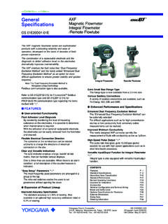
5 User GuideSPRUGV1 November 2010 Submit Documentation Feedback Chapter 1 IntroductionThe General-Purpose Input/Output (GPIO) peripheral provides dedicated General-Purpose pins that can be configured as either inputs or outputs. When configured as an output , you can write to an internal register to control the state driven on the output pin. When configured as an input , you can detect the state of the input by reading the state of an internal register. In addition, the GPIO peripheral can produce CPU interrupts and EDMA synchronization events in different interrupt/event generation modes. Figure 1-1 shows the GPIO peripheral block diagram. For an illustration of the GPIO peripheral in the DSP block diagram, see the device-specific data manual. Some GPIO pins are muxed with other device pins. For details on specific muxing and for the availability of the register bits, see the device-specific data manual. GPINT[0:15] are all available as synchronization events to the EDMA and as interrupt sources to the IntroductionSPRUGV1 November 2010 KeyStone Architecture general purpose Input/Output (GPIO) User Guide1-3 Submit Documentation Feedback Chapter 1 1-1 GPIO Peripheral Block DiagramA Some of the GPn pins are muxed with other device signals.
6 For details, see the device-specific data manual. B All GPINTn can be used as CPU interrupts and synchronization events to the EDMA. C The RIS_TRIG and FAL_TRIG registers are internal to the GPIO module and are not visible to the CPU. DIRSET_DA ATOUT_DA ATCLR_DATAS ynchronizationlogicPeripheral clock(CPU/6)DirectionSetdataOutputdataCl eardataIN_DA ATInputdataEdge detectionlogicInterrupt andEDMA event(GPINT)n(B)SET_RIS_TRIGRIS_TRIG(C)C LR_RIS_TRIGCLR_FAL_TRIGSET_FAL_TRIGFAL_T RIG(C)Data input /outputEDMA event andinterrupt generationSet risingedge triggerRising edgetriggerClear risingedge triggerSet fallingedge triggerFalling edgetriggerClear fallingedge triggerGPn(A)GPIO GPIO Function1-4 KeyStone Architecture general purpose Input/Output (GPIO) User GuideSPRUGV1 November 2010 Submit Documentation Feedback Chapter 1 GPIO FunctionYou can independently configure each GPIO pin (GPn) as either an input or an output using the GPIO direction registers.
7 The GPIO direction register (DIR) specifies the direction of each GPIO signal. Logic 0 indicates the GPIO pin is configured as output , and logic 1 indicates input . When configured as output , writing a 1 to a bit in the set data register drives the corresponding GPn to a logic-high state. Writing a 1 to a bit in the clear data register drives the corresponding GPn to a logic-low state. The output state of each GPn can also be directly controlled by writing to the output data register. For example, to set GP8 to a logic-high state, the software can perform one of the following: Write 0x100 to the SET_DATA register Read in OUT_DATA register, change the eighth bit to 1, and write the new value back to OUT_DATA To set GP8 to a logic-low state, the software can perform one of the following: Write 0x100 to the CLR_DATA register Read in OUT_DATA register, change the eighth bit to 0, and write the new value back to OUT_DATA Note that writing a 0 to bits in the set data and clear data registers does not affect the GPIO pin state.
8 Also, for GPIO pins configured as input , writing to the set data, clear data, or output data registers does not affect the pin state. For a GPIO pin configured as input , reading the input data register (IN_DATA) will return the pin state. Reading the SET_DATA register or the CLR_DATA data register will return the value in OUT_DATA, not the actual pin state. The pin state is available by reading the input data Interrupt and Event GenerationEach GPIO pin (GPn) can be configured to generate a CPU interrupt (GPINTn) and a synchronization event to the EDMA (GPINTn). The interrupt and EDMA event can be generated on the rising-edge, falling-edge, or on both edges of the GPIO signal. The edge detection logic is synchronized to the GPIO peripheral clock. The direction of the GPIO pin does not need to be input when using the pin to generate the interrupt and EDMA event. When the GPIO pin is configured as input , transitions on the pin trigger interrupts and EDMA events.
9 When the GPIO pin is configured as output , software can toggle the GPIO output register to change the pin state and in turn trigger the interrupt and EDMA event. Emulation Halt OperationSPRUGV1 November 2010 KeyStone Architecture general purpose Input/Output (GPIO) User Guide1-5 Submit Documentation Feedback Chapter 1 internal registers, RIS_TRIG and FAL_TRIG, specify which edge of the GPn signal generates an interrupt and EDMA event. Each bit in these two registers corresponds to a GPn pin. Table 1-1 describes the CPU interrupt and EDMA event generation of GPn pin based on the bit settings of the RIS_TRIG and FAL_TRIG registers. RIS_TRIG and FAL_TRIG are not directly accessible or visible to the CPU. These registers are accessed indirectly through four registers: SET_RIS_TRIG, CLR_RIS_TRIG, SET_FAL_TRIG, and CLR_FAL_TRIG. Writing 1 to a bit on the SET_RIS_TRIG register sets the corresponding bit on the RIS_TRIG register. Writing 1 to a bit of CLR_RIS_TRIG register clears the corresponding bit on the RIS_TRIG register.
10 Writing to SET_FAL_TRIG and CLR_FAL_TRIG works the same way on the FAL_TRIG register. Reading the SET_RIS_TRIG or CLR_RIS_TRIG register returns the value of RIS_TRIG register. Reading from SET_FAL_TRIG and CLR_FAL_TRIG register returns the value of FAL_TRIG register. To use the GPIO pins as sources for CPU interrupts and EDMA events, bit 0 in the bank interrupt enable register (BINTEN) must be set to 1. Emulation Halt OperationThe GPIO peripheral is not affected by emulation halts. Table 1-1 GPIO Interrupt and EDMA Event Configuration OptionsRIS_TRIG Bit nFAL_TRIG Bit nCPU Interrupt and EDMA Event Generation00 GPINTn interrupt and EDMA event is disabled01 GPINTn interrupt and EDMA event is triggered on falling edge of GPn signal10 GPINTn interrupt and EDMA event is triggered on rising edge of GPn signal11 GPINTn interrupt and EDMA event is triggered on both rising and falling edge of GPn signal End of Table Emulation Halt Operation1-6 KeyStone Architecture general purpose Input/Output (GPIO) User GuideSPRUGV1 November 2010 Submit Documentation Feedback Chapter 1 November 2010 KeyStone Architecture general purpose Input/Output (GPIO) User Guide2-1 Submit Documentation Feedback Chapter 2 Registers "Register Overview" on page 2-2 "GPIO Registers" on page Register Overview2-2 KeyStone Architecture general purpose Input/Output (GPIO)