Transcription of GENERAL RECOMMENDATIONS - gsengr.com
1 TECHNICAL INFORMATIONBULLETINN umber OneGENERAL RECOMMENDATIONSOn Sump Design For Obtaining Optimum Performance from pumps "Something is wrong with the pump-it ispulling in slugs of air."That remark is frequently made when a poorsump design has caused flow patterns whichresult in the formation of vortexes. A poorsump design will not only require abnormalsubmergences to overcome these vortexes,butcanalsocausecavitationanddet rimentally affect pump performance. Inmany cases the pumps are blamed forsomething that cannot be controlled in thedesign of the pumps . The best sump designappears to be also the most economicalsump design in that it will insure maximumoperating values for the pumping of good and bad sump design arepresented here in a simple diagramaticmanner.
2 Thisisa pictorial conclusion ofvarious investigations made by the Universityof California, Peerless Pump, and recently, little information was availableon sump design, and many features of sumplayouts still require additional study. Often theanalysis of a given sump design can only bemade by testing of a scale model of the ,makesumplayout arrangements per the principlesillustrated as shown onpage2under recommended sumpdesigns. The fundamental elementisthat the water shouldenter the pump chamber with am101mum of are shown at the bottom arrangements that willmake sudden changes in the direction offlow of water to the pumps .
3 Walls, pumpcolumns, channel openings, etc., can dis-turb the configuration of the sump floor shouldbe such that abrupt changes occur atleast five diameters fromthe side of thepump. The more distance from the pumpto the change in contour the better. Seesketches at the top of page must be flowing parallel to thesump walls when it reaches the sketches at right' of page columns andcross braces in thesump ahead of pumps whenever sump structural sump design velocity of1foot persecond at minimum water level is goodpractice. If some elements of goodpractice must be violated in a given sumpdesign, the detrimental effects may bereduced by lowering the velocity of flow inthe Pump Company2005 Dr Martin Luther King Jr.
4 Box 7026 Indianapolis, IN 46207-7026 RECOMMENDED SUMP DESIGNSR ecommended sump designs are illustrated in these diagrams. Whenever possible, make sump layout arrangementsin accordance with principles fundamental requirement is that the water should enter the pump chamber with a minimum ofturbulence and at a low DESIGNS TO BE AVOIDED2 Sump designs which are notrecommended are shown which makesuddenchangesinthedirection ofRowof water tothe pump are to be ,pumpcolumns,channel openings, etc., candisturb columns and crossbraces in the sump ahead ofpumps whenever supports as SUMP DESIGNCAVITATION, LOSS OF CAPACITY, NOISY OPERATIONand high maintenance expense,due to excessive wear, will result from steep "drop-offs" in approach channels as IN APPROACH CHANNELSto the sumps of large sewage pumps (left) causedserious disturbances of flow and induced vortices that reduced the efficiency of the pumps .
5 Abetter layout is shown at the SIDE INLET above the bottom of the circular sump of an irrigation pump resulted inturbulence and vorticesA sump designed for water velocity of 1 foot per sec. at minimum water level isgood practice. If some elements of good practice must be violated in a givensump application, the detrimental effects may be usually reduced by loweringthe velocity of flow in the OR ABRUPT BENDS andrestricted areas adjacent to the pumpintake invariably cause turbulence, sump design when flow isparallel to sump "Model sump tests";by R. H. Bird,Engineer, Peerless Pump Company"Air entrainment in pump suction inopen sumps";by H.
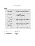
6 W. Iverson, AssistantProfessor of Mechanical Engineering,University of California, Berkeley, Calif."Studies of submergence requirementsof high specific speed pumps ";by H. , Assistant Professor of MechanicalEngineering, University of California,Berkeley, Calif. (ASME meeting 6-11-51)."Hydraulic problems encountered in theintake structures of vertical wet pit pumps ,and methods leading to their solution";by Fraser, Engineer, Worthington MAINCHANNELVELOCITYPUMPCAPACITYGPMRECOMM ENDEDMINIMUM "L"2' ,0009 FEET2' ,00013 FEET2' ,00018 FEET2' ,00022 FEET2' ,00028 FEET2' ,00039 FEET2' ,00046 FEET4' ,00011 FEET4' ,00016 FEET4' ,00022 FEET4' ,00027 FEET4' ,00034 FEET4' ,00047 FEET4' ,00059 FEETThe configuration of the sump floorshould be such that abrupt changesoccur at least five diameters fromthe side of the pump.
7 The moredistance from the pump to thechange in contour the better thepump suction entrance TYPE PROCESS PUMPType: Vertical, encased, close-coupled, single or multi-stagecentrifugalDescribed in Bulletin No. B-3400 CAPACITIES:Up to 3000 gpmHEADS:Up to1000feetDRIVES:As solid shaft orexplosion-proofmotors; steamturbineLIQUIDTEMPERATURE:Up to 400 FEspeciallydesigned forsystems with lowavailable NPSH(net positivesuction head)HYDRO-FOILT ypes: Single and multi-stagepropeller and mixed-flowDescribed in Bulletin No. B-300 CAPACITIES:600 to 220,000 GPMHEADS:2 to 60 feetDRIVES:Direct-connectedhollow shaftor solidshaft electric motors,belt and right anglegear drivefromstationary enginesAPPLICATION:Drainage, floodcontrol, circulating,industrial wastes;pumping from lakes,rivers, reservoirs,canals, :Choice of oil orwater lubrication4 VERTICAL INDUSTRIALPROCESS SERVICE PUMPType: Vertical, close coupled, singleor multi-stage, centrifugalDescribed in Bulletin No.
8 B-100 CAPACITIES:Up to 1400 gpmHEADS::Up to 300 psiLIQUIDS:Hydrocarbons,HANDLED:volatile liquids,chemicalsolutions, :Transfer service,pumpingfrom tanksand vesselsMATERIALSAny machinableOFalloy or applicationCONSTRUCTION:and liquid beingpumpedTIB #1 Revised 2-2006