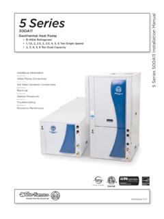
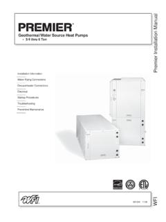
Transcription of Geothermal/Water Source Indoor Split Heat Pump 2 …
1 Installation InformationWater Piping ConnectionsHot Water Generation ConnectionsElectricalStartup ProceduresTroubleshootingPreventive MaintenanceIM1003SN 08/10 NSZ/NDZ Indoor Split Installation ManualGeothermal/Water Source Indoor Split Heat Pump 2 to 6 Tons Single Speed2 to 6 Tons Dual CapacityNSZ/NDZ Indoor Split INSTALLATION MANUALT able of ContentsModel Nomenclature ..4 Physical Characteristics ..4 Physical Dimensions ..5 General Installation Information ..6-9 Physical Data - Envision Air Handler ..9 Open Loop - Well Water Systems ..10-11 Water Quality ..11 Closed Loop - Ground Source Systems ..12 Hot Water Generator Connections ..13-14 Electrical Data ..15 Thermostat Wiring ..15 Wiring Schematics ..16-17 Microprocessor Control ..18-21 Operation Logic Data .. 22 DIP Switch Settings ..22 Refrigeration ..23-25 Line Set Sizes ..25 Pressure/Temperature Conversion Chart for R-410A ..26 Thermistor Resistance ..27 Operating Parameters ..27-28 Pressure Drop and Recommended Flow Rates.
2 29 Unit Startup and Troubleshooting ..30-32 Preventative Maintenance ..33 Replacement Procedures ..33 Service Parts List ..344 NSZ/NDZ Indoor Split INSTALLATION MANUAL Model Nomenclature123 4-67 8 9 1011 NDZ049A11 ACModel Type N = EnvisionCoax Options C = CopperCompressor Type N = Cupronickel D = Dual Capacity S = Single SpeedFuture Option A = StandardCabinet Configuration Z = Indoor SplitHot Water Option 0 = No Hot Water Generator, No IntelliStart 1 = Hot Water Generator with factory installed pump, No IntelliStart 3 = No Hot Water Generator, IntelliStart 4 = Hot Water Generator with factory installed pump, IntelliStartUnit CapacityVintage A = CurrentVoltage 1 = 208-230/60/1 Physical CharacteristicsModel02203003604204806007 002603804906472 Compressor (1 each)Single Speed ScrollDual Capacity Scroll Factory Charge R410a, oz [kg]5 6 [ ]5 6 [ ]5 6 [ ]74 [ ]9 0 [ ]9 2 [ ]1 0 8 [ ]5 2 [ ]5 6 [ ]9 0 [ ]9 2 [ ]104 [ ]Coax and Water Piping Water Connections Size - Swivel- in [mm]1 [ ]1 [ ] HWG Connection Size - Swivel - in [mm]1 [ ]1 [ ] Brass Service Valve - Liquid Line - in [mm]3/8 [ ]1/2 [ ]3/8 [ ]1/2[ ] Brass Service Valve - Suction Line - in [mm]5/8 [ ]3/4 [ ]7/8 [ ]5/8 [ ]3/4 [ ]7/8[ ] Coax and Piping Water Volume - gal [l]0.
3 7 [ ]1 .0 [ ]1 . 3 [ ]1 . 3 [ ]1 . 6 [ ]1 . 6 [ ]2 . 3 [ ]0 . 7 [ ]1 . 3 [ ]1 . 6 [ ]1 . 6 [ ] [ ] Weight - Operating, lb [kg]1 6 4 [74]1 74 [79]212 [96]2 1 3 [97]246 [112]2 5 1 [114]2 9 2 [132]189 [186]236 [107]250 [113]2 7 1 [123]290 [132] Weight - Packaged, lb [kg]1 8 4 [83]1 9 4 [88]232 [105]233 [106]266 [121]2 7 1 [123]3 1 2 [142]209 [95]256 [116]270 [122]2 9 1 [132]310 [141]10/29/08 NOTES: All units have TXV expansion devices, and 1/2 in. [ mm] and 3/4 in. [ mm] electrical knockouts. Brass service valves are sweat type valves. 5 NSZ/NDZ Indoor Split INSTALLATION MANUALP hysical Dimensions Dimensions are in molding and water connections extend in.
4 [ mm] beyond the front of the line connections extend 2 in. [ mm] beyond the front of the InWater OutService ValveHWG InHWG OutLow VoltageExternal PumpLine Indoor Split INSTALLATION MANUAL Installing and servicing heating and air conditioning equipment can be hazardous due to system pressure and electrical components. Only trained and qualified service personnel should install, repair or service heating and air conditioning equipment. Untrained personnel can perform the basic maintenance functions of cleaning coils and cleaning and replacing filters. All other operations should be performed by trained service personnel. When working on heating and air conditioning equipment, observe precautions in the literature, tags and labels attached to the unit and other safety precautions that may apply, such as the following safety measures:Follow all safety codes. Wear safety glasses and work gloves. Use a quenching cloth for brazing operations. Have a fire extinguisher available for all brazing operations.
5 Moving and StorageMove units in the normal up orientation. Units may be moved and stored per the information on the packaging. Do not stack more than three units in total height. Do not attempt to move units while stacked. When the equipment is received, all items should be carefully checked against the bill of lading to be sure all crates and cartons have been received. Examine units for shipping damage, removing the units from the packaging if necessary. Units in question should also be internally inspected. If any damage is noted, the carrier should make the proper notation on the delivery receipt, acknowledging the Location Locate the unit in an Indoor area that allows for easy removal of the access panels. Location should have enough space for service personnel to perform maintenance or repair. Provide sufficient room to make water, electrical and refrigerant line connections. Any access panel screws that would be difficult to remove after the unit is installed should be removed prior to setting the unit.
6 Care should be taken when units are located in unconditioned spaces to prevent damage from frozen water lines and excessive heat that could damage electrical Coil LocationRefer to the air handler manufacturer s instructions for the blower coil unit for details on installing the air handling portion of the DrainFollow the blower coil manufacturer s : Before performing service or maintenance operations on a system, turn off main power switches to the Indoor unit. If applicable, turn off the accessory heater power switch. Electrical shock could cause personal injury. Safety ConsiderationsDuct SystemAll blower coil units/air coils must be installed as specified by the manufacturer s installation instructions; however, the following recommendations should be considered to minimize noise and service air filter must always be installed upstream of the air coil on the return air side of the air handler or furnace. If there is limited access to the filter rack for normal maintenance, it is suggested that a return air filter grill be installed.
7 Be sure that the return duct is properly installed and free of leaks to prevent dirt and debris from bypassing the filter and plugging the air applications using galvanized metal ductwork, a flexible duct connector is recommended on both the supply and return air plenums to minimize vibration from the blower. To maximize sound attenuation of the unit blower, the supply and return plenums should include an internal duct liner of 1-inch thick glass fiber or be constructed of ductboard. Insulation is usually not installed in the supply branch ducts. Ducts in unconditioned areas should be wrapped with a minimum of 1-inch duct insulation. Application of the unit to uninsulated ductwork in an unconditioned space is not recommended as the unit s performance will be adversely affected. If the air handler is connected to existing ductwork, a previous check should have been made to assure that the duct system has the capacity to handle the air required for the unit application.
8 If ducting is too small, as in replacement of heating only systems, larger ductwork should be installed. All existing ductwork should be checked for leaks and repairs made accordingly. The duct systems and diffusers should be sized to handle the design airflow quietly. If air noise or excessive airflow is a problem, the blower speed can be changed to a lower speed to reduce airflow. This will reduce the performance of the unit slightly in heating; however, it will increase the temperature rise across the air coil. Airflow must still meet minimum SelectionThe following guidelines should be used when mating an Envision Split to an air R-410A components only. Select 13 SEER or higher air handler/coil. Match the air handler to the air handler coil data table. Indoor matching adjustable TXV should be used with any air handler/coil. Fixed orifice or cap tube systems should not be Existing Coil or Air HandlerIt is recommended that a new R-410A air handler be installed with an Envision Split considering the long term benefits of reliability, warranty, etc.
9 Versus the short term installation cost savings. However, the existing air handler may be retained provided the following:Coil currently is R-410A rated Coil uses a TXV. No capillary or fixed orifice systems should be usedGeneral Installation Information7 NSZ/NDZ Indoor Split INSTALLATION MANUALA life expectancy of more than 7 years remaining for the air handler and componentsFlush air coil and line set When utilizing the existing air coil or line set, only flushing compounds that vaporize should be used; which means they are packaged in a pressurized disposable cylinder. It is preferable to use a flushing agent that removes oil, water, and acid, plus, is biodegradeable and non-toxic. The flushing agent should be safe to use with both HCFC and HFC refrigerants. Once a flushing agent has been selected, follow the instructions provided with the first step should be purging the lines or air coil with nitrogen. Purging with nitrogen first will remove some of the particulate and residual oil which will allow the flushing agent to work better.
10 Never blow the flushing agent through a compressor, filter drier, or txv as it will cause the components to flushing is complete and the final system is assembled, an acid check should be preformed on the system. Acid test kits are available from most HVACR to Air CoilFigures 1 and 2 illustrate typical Envision Split installations. Reference the Line Set Sizes table for typical line set diameters and maximum length. Line sets over 60 feet are not recommended. Longer line sets will significantly reduce capacity and efficiency of the system as well as adversely effect the system reliability due to poor oil return. If the line set is kinked or deformed and cannot be reformed, the bad section of pipe should be replaced. A restricted line set will affect unit performance. As in all R-410A equipment, a reversible liquid line filter drier is required to insure all moisture is removed from the system. This drier should be replaced whenever breaking into the system for service.