Transcription of Getting Started Guide - Dell
1 dell NetworkingN1108T-ON/N1108P-ON/N1124T-ON/ N1124P-ON/N1148T-ON/N1148P-ONSwitchesGet ting Started GuideRegulatory Models: E17W and E18 WNotes, Cautions, and Warnings NOTE: A NOTE indicates important information that helps you make better use of your switch. CAUTION: A CAUTION indicates either potential damage to hardware or loss of data and tells you how to avoid the problem. WARNING: A WARNING indicates a potential for property damage, personal injury, or death. Lithium battery caution: There is a danger of explosion if a battery is incorrectly replaced. Replace only with the same or equivalent type. Dispose batteries of according to the manufacturer's instructions. Disposing a battery into fire, a hot oven, mechanically crushing, or cutting it can result in an explosion. Leaving a battery in an extremely hot environment can result in leakage of flammable liquid, gas, or an explosion. If a battery is subjected to extremely low air pressure, it may result in leakage of flammable liquid, gas, or an explosion.
2 The device can only be used in a fixed location such as a lab or a machine room. When you install the device, ensure that the protective earthing connection of the socket-outlet is verified by a skilled 2017 dell Inc. or its subsidiaries. All rights reserved. This product is protected by and international copyright and intellectual property laws. dell and the dell logo are trademarks of dell Inc. in the United States and/or other jurisdictions. All other marks and names mentioned herein may be trademarks of their respective Models: E17W and E18W May 2017P/N NTHM9 Rev. A00 Contents3 Contents1 Introduction.. 5N1100-ON Series Hardware Overview .. 5 Power Consumption for N1100-ON Series PoE Switches 5 Ventilation System .. 6N1100-ON Series Model Summary .. 62N1108T-ON/N1108P-ON Installation .. 7 Rack Mounting an N1108T-ON/N1108P-ON Switch.. 7 Installing in a Rack .. 73N1124T-ON/N1124P-ON/N1148T-ON/ N1148P-ON Installation.
3 9 Rack Mounting an N1124T-ON/N1124P-ON/ N1148T-ON/ N1148P-ON Switch .. 9 Installing in a Rack .. 9 Wall Installation for N1108T-ON and N1108P-ON.. 10 Installing as a Free-standing Switch.. 11 Stacking Multiple N1124T-ON/N1124P-ON/ N1148T-ON/ N1148P-ON Switches.. 124 Contents4 Starting and Configuring the N1100-ON Series Switch.. 13 Connecting an N1100-ON Series Switch to a Terminal. 14 Connecting an N1100-ON Series Switch to a Power Source 15AC and DC Power Connection .. 15 Booting the N1100-ON Series Switch.. 16 Performing the N1100-ON Series Initial Configuration. 17 Enabling Remote Management.. 17 Initial Configuration Procedure.. 18 Example Session .. 19 dell Easy Setup Wizard Console Example .. 20 Next Steps .. 245 NOM Information (Mexico Only) .. 26 Getting Started Guide5 Introduction This document provides basic information about the dell Networking N1100-ON Series switches, including how to install a switch and perform the initial configuration.
4 For information about how to configure and monitor switch features, refer to the User Configuration Guide , which is available on the dell Support website at See the Support website for the latest updates on documentation and firmware. NOTE: Switch administrators are strongly advised to maintain dell Networking switches on the latest version of the dell Networking Operating System (DNOS). dell Networking continually improves the features and functions of DNOS based on feedback from you, the customer. For critical infrastructure, pre-staging of the new release into a non-critical portion of the network is recommended to verify network configuration and operation with the new DNOS Series Hardware OverviewThis section contains information about device characteristics and modular hardware configurations for the dell Networking N1100-ON Series Consumption for N1100-ON Series PoE SwitchesTable 1-1 describes the power consumption for N1100-ON Series PoE switches.
5 The PoE power budget is 60W for the N1108P-ON, 185W for the N1124P-ON, and 370W for the Consumption for N1100-ON Series PoE SwitchesModelInput VoltagePower Supply ConfigurationMaximum Steady Current Consumption (A)Maximum Steady Power (W)N1108P-ON100V/60 HzMain PSU PSU PSU PSU PSU Started GuideVentilation SystemOne fan cools the N1108T-ON/N1108P-ON switches, and two fans cool the N1024T-ON/N1024P-ON/N1048T-ON/N1048P-ON switches. The fans are not field Series Model SummaryTable Series Switch Regulatory NumbersN1124P-ON100V/60 HzMain PSU PSU PSU PSU PSU PSU PSU PSU PSU PSU Model Name (MMN)DescriptionPower Supply Unit (PSU)Regulatory Model Number (RMN)Regulatory Ty p e N u m b e r (RTN)N1108T-ON 10x1G/2x1G SFP PortsDPS-24 GPE17WE17W001N1108P-ON 10x1G/2x1G SFP/2xPoE+ PortsDPS-80AP/ DPS-24 GPE17WE17W001 N1124T-ON 24x1G/4x10G SFP+ PortsDPS-40 APE18WE18W001 N1124P-ON 24x1G/4x10G SFP+/6xPoE+ PortsEDPS-250 BFE18WE18W001 N1148T-ON 48x1G/4x10G SFP+ PortsDPS-60 APE18WE18W002 N1148P-ON 48x1G/4x10G SFP+/12xPoE+ Port YM-2501DE18WE18W002 ModelInput VoltagePower Supply ConfigurationMaximum Steady Current Consumption (A)Maximum Steady Power (W) Getting Started Guide7N1108T-ON/N1108P-ON InstallationRack Mounting an N1108T-ON/N1108P-ON Switch WARNING.
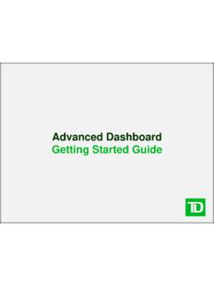
6 Read the safety information in the Safety and Regulatory Information as well as the safety information for other switches that connect to or support the switch. The AC power connector is on the rear panel of the in a Rack WARNING: Do not use rack mounting kits to suspend the switch from under a table or desk, or attach it to a wall. CAUTION: Disconnect all cables from the switch before continuing. Remove all self-adhesive pads from the underside of the switch, if they have been attached. CAUTION: When mounting multiple switches into a rack, mount the switches from the bottom the N1108T-ON/N1108P-ON switch in either the dell Rack Mount Kit as shown in Figure 1-1 or the dell Tandem Tray Kit as shown in Figure Rack Mount Kit8 Getting Started GuideFigure Tandem Tray Kit2 Insert the switch into the cm (19 inch) rack, ensuring that the rack mounting holes on the kit line up to the mounting holes in the the kit to the rack with either the rack bolts or cage nuts and cage-nut bolts with washers (depending on the kind of rack you have).
7 Fasten the bolts on the bottom before fastening the bolts on the Started Guide9N1124T-ON/N1124P-ON/N1148T-ON/ N1148P-ON InstallationRack Mounting an N1124T-ON/N1124P-ON/ N1148T-ON/ N1148P-ON Switch WARNING: Read the safety information in the Safety and Regulatory Information as well as the safety information for other switches that connect to or support the switch. The AC power connector is on the rear panel of the in a Rack WARNING: Do not use rack mounting kits to suspend the switch from under a table or desk, or attach it to a wall. CAUTION: Disconnect all cables from the switch before continuing. Remove all self-adhesive pads from the underside of the switch, if they have been attached. CAUTION: When mounting multiple switches into a rack, mount the switches from the bottom the supplied rack-mounting bracket on one side of the switch, ensuring that the mounting holes on the switch line up to the mounting holes in the rack-mounting bracket.
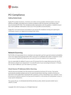
8 Figure 1-3 illustrates where to mount the the Brackets10 Getting Started Guide2 Insert the supplied bolts into the rack-mounting holes and tighten with a screwdriver. 3 Repeat the process for the rack-mounting bracket on the other side of the the switch into the cm (19 inch) rack, ensuring that the rack-mounting holes on the bracket line up with the mounting holes in the the bracket to the rack with either the rack bolts or cage nuts and cage-nut bolts with washers (depending on the kind of rack you have). Fasten the bolts on the bottom before fastening the bolts on the top. CAUTION: Make sure that the supplied rack bolts fit the pre-threaded holes in the rack. NOTE: Make sure that the ventilation holes are not Installation for N1108T-ON and N1108P-ONTo m o u n t t h e s w i t c h o n a w a l l :1 Make sure that the mounting location meets the following requirements: The surface of the wall must be capable of supporting the switch.
9 Allow at least two inches ( cm) space on the sides for proper ventilation and five inches ( cm) at the back for power cable clearance. The location must be ventilated to prevent heat the supplied wall-mounting bracket on one side of the switch, verifying that the mounting holes on the switch line up to the mounting holes on the wall-mounting bracket. Getting Started Guide11 Figure Installation for Wall Mounting3 Insert the supplied screws into the wall-mounting bracket holes and tighten with an M5x32 the process for the wall-mounting bracket on the other side of the the switch on the wall in the location where the switch is being the wall mark the locations where the screws to hold the switch must be the marked locations, drill the holes and place all plugs (not provided) in the the switch to the concrete wall or wood material with screws (not provided). Make sure that the ventilation holes are not as a Free-standing Switch NOTE: dell strongly recommends mounting the switch in a the switch on a flat surface if you are not installing it in a rack.
10 The surface must be able to support the weight of the switch and the switch cables. The switch is supplied with four self-adhesive rubber pads. 1 Attach the self-adhesive rubber pads on each location marked on the bottom of the Started Guide2 Set the switch on a flat surface, and make sure that it has proper ventilation by leaving 5 cm (2 inches) on each side and 13 cm (5 inches) at the back. Stacking Multiple N1124T-ON/N1124P-ON/ N1148T-ON/ N1148P-ON SwitchesYou can stack N1124T-ON/N1124P-ON/N1148T-ON/ N1148P-ON switches up to four switches high using 10G SFP+ ports on the front of the switch. The ports must be configured to support stacking. When multiple switches are connected together through the stack ports, they operate as a single unit with up to 208 front-panel ports. The stack operates and is managed as a single entity. Refer to the User Configuration Guide and the CLI Reference Guide for more Started Guide13 Starting and Configuring the N1100-ON Series SwitchThe following flow chart provides an overview of the steps you use to perform the initial configuration after the switch is unpacked and and Configuration Flow Chart14 Getting Started GuideConnecting an N1100-ON Series Switch to a TerminalAfter completing all external connections, configure the switch by connecting it to a terminal.