Transcription of GT24C64 2-WIRE 64K Bits Serial EEPROM - Giantec …
1 GT24C64 Copyright 2013 Giantec Semiconductor Inc. ( Giantec ). All rights reserved. Giantec reserves the right to make changes to this specification and its products at any time without notice. Giantec products are not designed, intended, authorized or warranted for use as components in systems or equipment intended for critical medical or surgical equipment, aerospace or military, or other applications planned to support or sustain life. It is the customer's obligation to optimize the design in their own products for the best performance and optimization on the functionality and etc. Giantec assumes no liability arising out of the application or use of any information, products or services described herein. Customers are advised to obtain the latest version of this device specification before relying on any published information and prior placing orders for products. Giantec Semiconductor, Inc.
2 V0 1/23 GT24C64 2-WIRE 64K Bits Serial EEPROM GT24C64 Giantec Semiconductor, Inc. v0 2/23 Table of Contents 1. Features .. 3 2. General Description .. 3 3. Functional Block Diagram .. 4 4. Pin 5 8-Pin SOIC/SOP, TSSOP, PDIP and MSOP .. 5 8-Lead UDFN .. 5 Pin Definition .. 5 Pin Descriptions .. 5 5. Device Operation .. 6 2-WIRE Bus .. 6 The Bus Protocol .. 6 Start Condition .. 6 Stop Condition .. 6 Acknowledge .. 6 Reset .. 6 Standby Mode .. 6 Device Addressing .. 6 Write Operation .. 6 Read Operation .. 7 Diagrams .. 8 Timing Diagrams .. 11 6. Electrical Characteristics .. 12 Absolute Maximum Ratings .. 12 Operating Range .. 12 Capacitance .. 12 DC Electrical Characteristic .. 13 AC Electrical Characteristic.
3 14 7. Ordering Information .. 15 8. Top Markings .. 16 SOIC/SOP package .. 16 TSSOP package .. 16 PDIP package .. 16 UDFN package .. 16 MSOP package .. 17 9. Package Information .. 18 SOIC/SOP .. 18 TSSOP .. 19 PDIP .. 20 UDFN .. 21 MSOP .. 22 10. Revision History .. 23 GT24C64 Giantec Semiconductor, Inc. v0 3/23 1. Features Two- wire Serial Interface, I2 CTM compatible Bi-directional data transfer protocol Wide-voltage Operation VCC = to Speed: 400 KHz ( ) and 1 MHz ( ~ ) Standby current (max.): 1 A, Operating current (max.): 3 mA, Hardware Data Protection Write Protect Pin Sequential & Random Read Features Memory organization: 64Kb (8,192 x 8) Page Size: 32 bytes Page write mode Partial page writes allowed Self timed write cycle: 5 ms (max.)
4 Noise immunity on inputs, besides Schmitt trigger High-reliability Endurance: 1 million cycles Data retention: 100 years Industrial grade Packages: SOIC/SOP, TSSOP, PDIP, UDFN, MSOP and CSP Lead-free, RoHS, Halogen free, Green 2. General Description The GT24C64 is an industrial standard electrically erasable programmable read only memory ( EEPROM ) device that utilizes the industrial standard 2-WIRE interface for communications. The GT24C64 contains a memory array of 64K bits (8,192x8), which is organized in 32-byte per page. The EEPROM operates in a wide voltage range from to , which fits most application. The product provides low-power operations and low standby current. The device is offered in Lead-free, RoHS, halogen free or Green package. The available package types are 8-pin SOIC/SOP, TSSOP, PDIP, UDFN, MSOP and CSP.
5 The GT24C64 is compatible to the standard 2-WIRE bus protocol. The simple bus consists of Serial Clock (SCL) and Serial Data (SDA) signals. Utilizing such bus protocol, a Master device, such as a microcontroller, can usually control one or more Slave devices, alike this GT24C64 . The bit stream over the SDA line includes a series of bytes, which identifies a particular Slave device, an instruction, an address within that Slave device, and a series of data, if appropriate. The GT24C64 also has a Write Protect function via WP pin to cease from overwriting the data stored inside the memory array. In order to refrain the state machine from entering into a wrong state during power-up sequence or a power toggle off-on condition, a power on reset circuit is embedded. During power-up, the device does not respond to any instructions until the supply voltage (VCC) has reached an acceptable stable level above the reset threshold voltage.
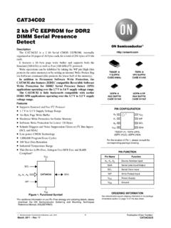
6 Once VCC passes the power on reset threshold, the device is reset and enters into the Standby mode. This would also avoid any inadvertent Write operations during power-up stage. During power-down process, the device will enter into standby mode, once VCC drops below the power on reset threshold voltage. In addition, the device will be in standby mode after receiving the Stop command, provided that no internal write operation is in progress. Nevertheless, it is illegal to send a command unless the VCC is within its operating level. GT24C64 Giantec Semiconductor, Inc. v0 4/23 3. Functional Block Diagram GT24C64 Giantec Semiconductor, Inc. v0 5/23 4. Pin Configuration 8-Pin SOIC/SOP, TSSOP, PDIP and MSOP To p V i e w A0A1 VCCSCLSDAGNDA2WP12348765 8-Lead UDFN To p V i e w A0A1 VCCSCLSDAGNDA2WP12348765 Pin Definition Pin No.
7 Pin Name I/O Definition 1 A0 I Device Address Input 2 A1 I Device Address Input 3 A2 I Device Address Input 4 GND - Ground 5 SDA I/O Serial Address and Data input and Data out put 6 SCL I Serial Clock Input 7 WP I Write Protect Input 8 VCC - Power Supply Pin Descriptions SCL This input clock pin is used to synchronize the data transfer to and from the device.
8 SDA The SDA is a bi-directional pin used to transfer addresses and data into and out of the device. The SDA pin is an open drain output and can be wired with other open drain or open collector outputs. However, the SDA pin requires a pull-up resistor connected to the power supply. A0, A1, A2 The A0, A1 and A2 are the device address inputs. Typically, the A0, A1, and A2 pins are for hardware addressing and a total of 8 devices can be connected on a single bus system. When A0, A1, and A2 are left floating, the inputs are defaulted to zero. WP WP is the Write Protect pin. While the WP pin is connected to the power supply of GT24C64 , the entire array becomes Write Protected ( the device becomes Read only). When WP is tied to Ground or left floating, the normal write operations are allowed. VCC Supply voltage GND Ground of supply voltage GT24C64 Giantec Semiconductor, Inc.
9 V0 6/23 5. Device Operation The GT24C64 Serial interface supports communications using industrial standard 2-WIRE bus protocol, such as I2C. 2-WIRE Bus The two- wire bus is defined as Serial Data (SDA), and Serial Clock (SCL). The protocol defines any device that sends data onto the SDA bus as a transmitter, and the receiving devices as receivers. The bus is controlled by Master device that generates the SCL, controls the bus access, and generates the Start and Stop conditions. The GT24C64 is the Slave device. The Bus Protocol Data transfer may be initiated only when the bus is not busy. During a data transfer, the SDA line must remain stable whenever the SCL line is high. Any changes in the SDA line while the SCL line is high will be interpreted as a Start or Stop condition.
10 The state of the SDA line represents valid data after a Start condition. The SDA line must be stable for the duration of the High period of the clock signal. The data on the SDA line may be changed during the Low period of the clock signal. There is one clock pulse per bit of data. Each data transfer is initiated with a Start condition and terminated by a Stop condition. Start Condition The Start condition precedes all commands to the device and is defined as a High to Low transition of SDA when SCL is High. The EEPROM monitors the SDA and SCL lines and will not respond until the Start condition is met. Stop Condition The Stop condition is defined as a Low to High transition of SDA when SCL is High. All operations must end with a Stop condition. Acknowledge After a successful data transfer, each receiving device is required to generate an ACK. The Acknowledging device pulls down the SDA line.