Transcription of Heat Trace Design Guide - ARCO Engineering
1 Chromalox PRECISION heat AND CONTROLE lectrical heat Tracing SystemsDesign GuideCONTENTSINTRODUCTIONThis Design Guide provides a step-by-stepapproach for the Design , specification, and selec-tion of a bill of materials for an electric heat tracing system. Electric heat tracing systems aredesigned to make up for the heat lost fromprocess system equipmentthrough the thermal some cases, the heat tracingsystem can be used for systemheat-up at initial startup or after apower information in this Design Guide will allow theuser to Design , specify, and select a complete bill ofmaterials for freeze protection or process mainte-nance applications for a piping system or tank. Byfollowing the steps in this Guide the user can easilyselect a complete bill of materials forthe system, including heating cable,connection accessories, andtemperature OFThermal Design - Pipes: .. 1 Thermal Design - Tanks:.. 6 Heating Cable Selection.
2 8 Mineral Insulated CableDesign: .. 17 Electrical Design : .. 18 Component Selection and Accessories: .. 24 Control Selection:.. 32 IntelliTRACE Controls .. 36 TABLE OFCONTENTSTHERMAL Design PIPES1 The first step in designing a heat Trace system isto determine the heat loss from each pipe or tankto be traced. Collect the following data for eachpipe (for tank applications go to page 6). Then fol-low the steps below to determine the heat Temperature, Tm:Minimum Ambient Temperature, Ta:Location, Indoor / Outdoor:Wind Speed, if applicable:Nominal Pipe / Tubing Size, DP:Additional Safety Factor,if required:Thermal Insulation Type and Thickness:Example:EnglishMaintenance Temperature, Tm:40 FMinimum Ambient Temperature, Ta:-20 FLocation, Indoor / Outdoor:OutdoorWind Speed, if applicable:10 mphNominal Pipe / Tubing Size, DP:3" SteelAdditional Safety Factor,if required:NoneThermal Insulation Type2"and Thickness:Cellular GlassExample:MetricMaintenance Temperature, CMinimum Ambient Temperature, CLocation, Indoor / Outdoor:OutdoorWind Speed, if applicable:16 kphNominal Pipe / Tubing Size, DP:76 mm SteelAdditional Safety Factor,if required:NoneThermal Insulation Type51 mmand Thickness.
3 Cellular GlassStep T T = Tm- TaEnglish= 40 F - (-20 F)= 60 FMetric= C - ( C)= CStep Pipe heat LossFind QPin Table 1 (page 2) for the nominal pipesize and insulation thickness based on example, for a 3" (76 mm) pipe with 2" (51 mm) insulation and T = 60 F ( C),the value for QPis W/ft ( W/m).THERMAL Design -PIPESStep for InsulationTable 1 (page 2) is based on ASTM C547 Fiberglas , as found in the step above, must be adjusted for the insulation type. Multiply your heat loss by Ia,the Insulation Adjustment Factor, from the values inTable 2 (page 5).QF= QPx IaFor Cellular Glass, Ia= W/ft x W/ftMetricQF= W/m x W/mStep for Indoor Location / Windspeed If location is indoors multiply QFby for Additional Safety FactorTable 1 is based on 10% safety factor and 20 mph(32 kph) windspeed, add 5% margin for each 5 mph (8 kph) over 20 mph (32 kph).THERMAL Design -PIPES2 THERMAL Design -PIPEST able 1 Pipe heat Loss (QP) in W / ft and W/m Based on Temperature Differential and Insulation ThicknessNominalPipe Size,in.
4 (ID) mm (OD)Temperature Difference Between Pipe and AmbientDeg F40 F50 F60 F70 F80 F90 F100 F120 F140 F160 F180 F200 F220 F240 F260 FSiDeg C C C C C C1" ( mm) Insulation Thickness1/2" " " " " " " " " " " " " " " " " " Design -PIPEST emperature Difference Between Pipe and AmbientDeg F40 F50 F60 F70 F80 F90 F100 F120 F140 F160 F180 F200 F220 F240 F260 FSiDeg C C C C C C " (38 mm) Insulation Thickness1/2" " " " " " " " " " " " " " " " " " 1 cont' Size,in. (ID) mm (OD)Temperature Difference Between Pipe and AmbientDeg F40 F50 F60 F70 F80 F90 F100 F120 F140 F160 F180 F200 F220 F240 F260 FSiDeg C C C C C C2" ( ) Insulation Thickness1/2" " " " " " " " " " " " " " " " " " Design -PIPEST able 1 cont' Size,in.
5 (ID) mm (OD)5 THERMAL Design -PIPEST emperature Difference Between Pipe and AmbientDeg F40 F50 F60 F70 F80 F90 F100 F120 F140 F160 F180 F200 F220 F240 F260 FSiDeg C C C C C C3" ( mm) Insulation Thickness1/2" " " " " " " " " " " " " " " " " 1 cont' Size,in. (ID) mm (OD)Pipe Insulation TypeInsulation AdjustmentFactorGlass fiber (ASTM C547) silicate (ASTM C533) glass (ASTM C552) cellular urethane (ASTM C591) elastomer (ASTM C534) fiber blanket (ASTM C553) perlite (ASTM C610) 2 Insulation Adjustment FactorsCollect the following information for each Temperature, Tm:Minimum Ambient Temperature, Ta:Location, Indoor / Outdoor:Wind Speed, if applicable:Tank Shape and Surface Area:Additional Safety Factor,if required:Thermal Insulation Type and Thickness:Example:EnglishMaintenance Temperature, Tm:40 FMinimum Ambient Temperature, Ta:-20 FLocation, Indoor / Outdoor:OutdoorWind Speed, if applicable:20 mphTank Shape and Surface Area:Steel Horizontal Cylinder 3 ft ft longAdditional Safety Factor,if required:NoneThermal Insulation Type 2"and Thickness:Cellular GlassExample:MetricMaintenance Temperature, CMinimum Ambient Temperature, CLocation, Indoor / Outdoor.
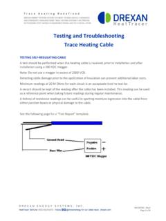
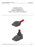
6 OutdoorWind Speed, if applicable:32 kphTank Shape and Surface Area:Steel Horizontal Cylinder m m longAdditional Safety Factor,if required:NoneThermal Insulation Type 51 mmand Thickness:Cellular GlassStep T T = Tm- TaEnglish= 40 F - (-20 F)= 60 FMetric= C - ( C)= CTHERMAL Design TANKS6 THERMAL Design -TANKSRECTANGULAR TANKAREA = AREA (TOP) + AREA (SIDE)+ AREA (BOTTOM)= 2(WH+HL+WL)WLHCYLINDRICAL TANK, CONICALAREA = AREA (TOP) + AREA (SIDE)+ AREA (CONE)= D2/4 + DH+ ( /2)(D+d)(D d)24+h2 SdHDCYLINDRICAL TANK, DISHEDAREA = AREA (TOP) + AREA (SIDE)+ AREA (BOTTOM)= ( /4)(D2+4h2) + DH+ D2/4 DHhCYLINDRICAL TANK, FLATAREA = AREA (ENDS) + AREA (SIDE) = D2/2 + DHHDI nsulation ThicknessHeat Loss (QT) FW/m2/ C1 3 heat Loss (QT) for Various Insulation ThicknessesNOTE: heat loss values based on 20 mph (32 kph) wind, 10% safetyfactor, and Fiberglas insulation at 50 F (10 C).THERMAL Design -TANKS7 Step Total Surface Area of TankMost tanks are a combination of the surface area of each section andthen add the areas for each section to determinethe overall surface area, = D2/2 + DHEnglish= ( ) (3 ft)2/2 + ( )(3 ft) (6 ft)= ft2 Metric= ( ) ( m)2/2 + ( )( m) ( m)= m2 Step QTFind QTin Table 3 for the corresponding heat Loss, QQ = (QT)( T) (A)English= ( W/ft2/ F) (60 F) ( ft2)= 170 WMetric= ( W/m2/ C) ( C) ( )= 170 WStep for InsulationQ, as found in the step above, must be adjustedfor the insulation type.
7 Multiply your heat loss byIa, the Insulation Adjustment Factor, from the val-ues in Table the Insulation Adjustment Factor (Ia) for cel-lular glass ( ):QF= Q x Ia= 170 W x 252 WStep for Indoor Location / WindspeedIf the application is indoors, multiply QFby Table 3 is based on 20 mph (32 kph) wind-speed, add 5% margin for each additional 5 mph (8 kph) over 20 mph (32 kph).Step for Additional Safety FactorsStep Equipment heat LossesEquipment such as ladders, manways, and supportlegs act as heat sinks and increase the overallheat loss of the tanks. For each piece of equip-ment, use Table 4 to calculate equipment heat loss and add to the heat loss calculated Design -TANKSFor example, additional heat loss for 4 support legs:QA= (QS) ( T) x number of legsEnglish= ( W/ F)(60 F) x 4= 120 WMetric= ( W/ C)( /C) x 4= 120 WStep the Cable Length RequiredTo determine the length required, take the totalheat loss as calculated in the previous steps anddivide by the chosen cable output at the mainte-nance temperature.
8 (See Figures 1-4.)Q = QF+ QA= 252 W + 120 W= 372 WSupport Legs W/ F ( W/ C) x number of W/ F ( W/ C) x number of W/ F ( W/ C) x number of manwaysTable 4 Tank Equipment heat Loss Calculation (QS)SRL5-CT Output @ 40 F = W/ftL = 372 W W/ftL = 78 ftTo determine the correct cable for your application,determine the following information:Maintenance Temperature =Max. Exposure Temperature =Pipe Material =Service Voltage =Chemical Environment =Area Classification = heat Requirement (from Thermal Design Section) =8 Example:MetricMaintenance Temperature = CMax. Exposure Temperature = CPipe Material =Stainless SteelService Voltage =120 VChemical Environment =OrganicArea Classification =CID2 Group BHeat Requirement (from Thermal Design Section) = W/mStep Heating Cable Family Based on the maximum maintainance temperature,maximum exposure temperature, and area classifi-cation, select the heating cable family from Table : Maximum maintenance temperatures forconstant wattage cables (CWM) are dependentupon cable wattage rating and the use of alumi-um foil tape.
9 See Table 6 (page 10).Example:Based on information, select the SRL (Self-Regulating Low Temperature) Cable : SRL * - * *HEATING CABLESELECTIONHEATING CABLESELECTIONHEATING CABLE SELECTIONE xample:EnglishMaintenance Temperature =40 FMax. Exposure Temperature =100 FPipe Material =Stainless SteelService Voltage =120 VChemical Environment =OrganicArea Classification =CID2 Group BHeat Requirement (from Thermal Design Section) = W / ft9 HEATING CABLESELECTIONNOTE: It is the responsibility of the facility manageror engineer to determine the classification of an area where heat tracewill be installed. The factory can help determine a suitable cable based on the information CableFamilyAreaClassificationPipeMateria lMaximum MaintenanceTemperature F CMaximumExposureTemperature(Power Off) F COrdinary Plastic/Metal150 F 65 C185 F85 CUL, CSA, FMGOST, Cenelec,CE, ATEXC lass I, Div. 2,CSA, FMGOST, Cenelec,Gr.
10 B, C, D(Gr. A, CSA Only)CE, ATEXC lass II, Div. 2,CSA, FMGOST, CenelecGr. E, F, G(Gr. E, CSA Only)CEClass III, Div. 2,FM OnlyGOST, Cenelec,CE, ATEXO rdinaryMetal Only302 F150 C 420 F215 CUL, CSA, FMGOST, Cenelec,CE, ATEXC lass I Div. 2,CSA, FMGOST, Cenelec,Gr. A, B, C, D,(Gr. A, CSA Only)CE, ATEXC lass II, Div. 2,CSA OnlyGOST, Cenelec,Gr. F, GCE, ATEXC lass I, Div. 1,Plastic/Metal150 F 66 C185 F 85 CFM ,C,DClass II, Div. 1,FM ,F,GClass III, Div. 1FM OnlyClass I, Div. 1,Metal Only302 F 150 C420 F 215 CFM ,C,DClass II, Div. 1,FM ,F,GClass III, Div. 1FM OnlyOrdinaryMetal OnlySee Table 4392 F200 CUL, CSAH azardousArea ConsultFactoryOrdinaryMetal OnlySee Section1,100 F 593 CHazardousArea ConsultFactorySRL(Self-RegulatingLow Temperature) (Self-RegulatingMediumTemperature)HSRL(H -Self-Regulating LowTemperature)HSRM(H-Self-Regulating MediumTemperature)CWM(ConstantWattage)MI (MineralInsulated)Table 5 Heating Cable FamiliesConsult FactoryConsult Factory10 HEATING CABLESELECTIONT able 6 Maximum Maintenance Temperatures for Constant Wattage Cables (CWM)Step Heating Cable ConstructionOptionsSelect from Table 7 the appropriate constructionoption for the desired level of mechanical and corrosive chemical option cable is constructed with a tinned coppergrounding braid option cable is constructed with a tinned cop-per braid and polyolefin option cable is constructed with a tinned cop-per braid and fluoropolymer.