Transcription of High Voltage and Load Current Monitors
1 APPLICATION NOTE 8 PAGE 1 high Voltage and load Current Monitors This Application Note describes how high Voltage and load Current Monitors work with all EMCO Warning high Voltage power supplies present a serious risk of personal injury if not used in accordance with design and/or use specifications, if used in applications on products for which they are not intended or designed, or if they are used by untrained or unqualified personnel. For more information, please refer to the EMCO Safety Warning and Disclaimer located at: EMCO HV DC-DC converters generate a high - Voltage output based on the Voltage at the input pin (for proportional models) or the programming pin (for regulated models).
2 Since the relationship between input or programming Voltage and the high Voltage output is a linear function, it s sufficient in most cases to set and verify the input (or programming) Voltage . Once the input Voltage is set, output volt-age remains constant if the load impedance is stable. For applications where output Voltage monitoring is required, either to verify that critical limits are not exceeded or to control a proportional unit through a feedback loop, simple OP-AMP based circuits can provide the functionality.
3 In applications where output Current sensing is required to detect fault or threshold limit conditions, the OP-AMP circuits for Voltage monitoring can be modified slightly to provide the Current monitor functionality. This application note will describe simple Voltage and Current monitor circuits and provide measured performance data for specific MonitoringOutput Voltage monitoring is accomplished by divid-ing the high - Voltage (HV) at the output terminal by a large-ratio resistor divider and then buffering the resulting Voltage with a Voltage -follower.
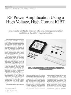
4 A high value resistance for the divider will minimize Current draw from the converter and maximize Current available to the load . A sample Voltage monitor circuit for positive output models is shown in Figure +OUTPUTU1 TLV247 XAVMONR210kR1 100M++-Figure 1. Positive Output Voltage MonitorAPPLICATION NOTE 8 PAGE 2 Voltage monitor Positive OutputIn this specific Voltage monitor implementation, the divider ratio is 1:10000 and a +10kV output from an EMCO converter is reduced to 1V at the input to the Voltage follower.
5 The tolerance of the resistors is the primary factor affecting the accuracy of the monitor . A cost-effective tradeoff is to use 1% resis-tors which leads to a ~1% accuracy in the monitor Voltage . The 100M resistor needs to have a Voltage rating exceeding the maximum Voltage of the HV converter. In this case, a 20kV-rated axial thick-film resistor is suitable. As EMCO HV converters require input voltages ranging from 5 to 24V, the moni-tor circuit uses a single-supply OP-AMP to avoid requirement of a negative supply Voltage .
6 In using a single-supply OP-AMP to buffer a Voltage near ground, it s important that the OP-AMP have rail-to-rail inputs and outputs. For EMCO models operating from a 5V input, the TLV247X OP-AMPs enable a lin-ear transfer function in the Voltage follower for HV output from 500V to 10kV. The low input bias Current and low input offset Voltage of this OP-AMP family aid to keep the accuracy at ~1%. For EMCO mod-els operating at 12V, 15V, or 24V, an OPA171/2171 OP-AMP can be used in the Voltage follower. This family of OP-AMPs operates from to 36V and tight performance specifications are maintained for an input Voltage from the negative rail to within 2V of the positive monitor Negative OutputFor EMCO models with a negative high Voltage output, the monitor circuit may need to generate a positive monitor Voltage from a divided negative output Voltage .
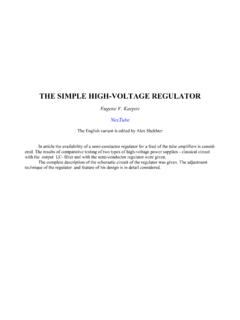
7 A single-supply inverting amplifier is sufficient for this purpose if the OP-AMP has rail-to-rail inputs and outputs. A sample Voltage monitor circuit for negative output models operating from 5V is shown in Figure input impedance of the inverting amplifier affects the resistor divider accuracy and reduces the divided Voltage from the intended 1:10000 ratio. The gain of the inverting amplifier is adjusted to great-er than unity to compensate for the reduced divider Voltage . The result is a monitor circuit with a linear transfer function for HV output from -500V to -10kV.
8 For negative-output EMCO models operating at 12V, 15V, or 24V, an OPA171/2171 OP-AMP can be used in the inverting amplifier. For protection of the OP-AMP at power-down, a Schottky diode to ground can be placed at the inverting input. To minimize the impact on monitor accuracy, the diode should have low leakage Current (<= ).Figure 2. Negative Output Voltage MonitorR3 60kR4 50K-OUTPUTU1 TLV247 XAVMONVCCR210kR1 100M-++APPLICATION NOTE 8 PAGE 3 Voltage monitor Prototypes and Test ResultsVoltage Monitors were built for a positive and a negative Q-Series model.
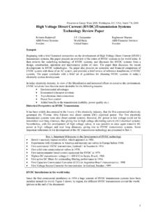
9 One unit per model was tested using the EMCO production test bench. A Voltage transfer function under full load was captured using both the test bench and the Voltage monitor circuit. The production test bench results are consid-ered accurate. The difference between the two sets of measured voltages is the Voltage monitor error. The Voltage monitor readings and error percentages for the Q12-5 and Q20N-5 DC-DC converters are plotted below. The monitor error is worst at DC-DC converter turn-on and decreases to less than 2% when Vin is half the rated input Voltage .
10 (As rated output Voltage for the selected models is much less than 10kV, adjustments were made to resistor values in the schematics above to scale the monitor Voltage to >1V). % errorVmonVinQ12-5 Voltage MonitorVmon% % errorVmonVinQ20N-5 Voltage MonitorVmon% errorFigure 3. Voltage monitor Test ResultsAPPLICATION NOTE 8 PAGE 4 Current MonitoringIn applications where output Current sensing is required, the Voltage monitor circuits described can be modified to measure Current . It is quite difficult to employ high -side sensing techniques to measure Current because of the high voltages involved.