Transcription of How To: Matching Devices - FIRST WATT
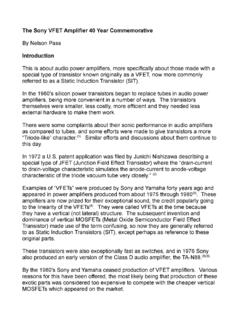
1 After you acquire the Devices , you will need to test them. You might consider running lots of tests on these transistors, but only one is essential: measuring gate-source voltage versus current. The greatest variations occur here, and it is necessary to do some Matching to get proper performance. This test will also tell you whether or not the device is test is simple and requires a power supply, a resistor, and a DC voltmeter. Figure 12 shows the test hookup for N- and P-channel types. The supply source resistance (R1) is nominal, and is found from I = (V - 4)/R1. Consistency is the most important thing here.
2 The given voltage is 15 and, adjusting for about a 4V VGS, we will see about 11V across the are looking for as much Matching of the input MOSFETs as possible at a current of 5mA. For this test, we use an R1 value of Measure the voltage between the gate and the source. Write it down on a piece of masking tape or a sticky label and place it on the part. Keep in mind the caveats about electrostatic discharge: touch ground before you touch the input MOSFETs is critical, because they must share equally the 10mA of bias current from the current source, and they will not do that unless their VGS is matched.
3 At 5mA current, they have an equivalent source resistance of about 15ohm. Assuming we want them to share the current to within 2mA, we calculate the required VGS match as follows. Using the formula V = IR, we see V = x 15, which gives us 30mV. The VGS of the input Devices should be matched to within 30mV at 5mA current. The Matching is only essential within a given pair; you do not have to match the Ps to the Ns, or match to Devices in another you are unable to find input Devices matched to within 30mV, you must insert resistance in the source to make up the difference.
4 The resistance is calculated by the difference of the two values of VGS divided by 5mA. For example, if the difference in VP1GS is 100mV, then = 20ohm. You would then place 20ohm in series with the MOSFET source having the lower use the same test setup for the MOSFETs in the TO-220 packages but at a higher current (20mA), so we use a 560ohm resistor. No Matching is required for these Devices ; we are just checking to see that the VGS is between and that they will measure the output device VGS at about 170mA. You can achieve this with either a 56ohm at 2W resistor, or two 100ohm at 1W resistors in parallel.
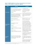
5 We are looking to obtain a reasonable match within a parallel output bank of each polarity of each channel, so we want two groups of 12 with matched N- channel Devices , and two groups of matched P-channel To: Matching Devices : 1993, Nelson PassPass Labs: Articles: how to match Devicespage 1 The VGS voltages of our test samples gave the following spread: N-channel ---- P-channelMin. VGS ---- ------ VGS --- ------ VGS ------ also measured the transconductance by taking another reading for each device at a higher current ( ), just to see what kind of variation we got.
6 The transconductances measured from a low of to a high of , with the average at about Within this amplifier s general operating curve, each output will vary its current by about for every volt of its VGS change. For 12 Devices in parallel, we expect about 15A for each such placing 1ohm source resistors on each transistor, we can assure adequate current sharing for a fairly wide range of VGS. In Class A bias, we will be operating at about 200mA/device, which will place across each source resistor. A variation in VGS will cause the bias to be unequally distributed between the Devices .
7 For example, for a device in parallel with a device, the FIRST will run at about 160mA at 6W and the second at about 240mA at that each of these Devices is rated at 75W on a cold heatsink, and maybe 50W on a hot sink. We are only going to bias them to about 8W each, so they re not going to break from a little unequal distribution. Nevertheless, we like to see the load shared, and recommend that you group the outputs by VGS as closely as possible. Matching within will work, and is even better. Within a population of 150 transistors, you can easily get 12 sets matched to VGS at 200mA.
8 Pass Labs: Articles: how to match Devicespage 2