Transcription of HWB HW 300-670 211683 0905 - Water Heaters
1 11111 PLACE THESE INSTRUCTIONS ADJACENT TO BOILER ANDNOTIFY OWNER TO KEEP FOR FUTURE REFERENCEA DIVISION OF SMITH CORPORATIONMC BEE, SC SEATTLE, WASTRATFORD, ONTARIOVELDHOVEN, THE NO. 211683 -000 IN 0905 SUPERSEDES PART NO'S, 210288-000 REV. 01 & 192356-000 GAS-FIRED COMMERCIAL COPPER BOILERS FORHYDRONIC HEATING AND HOT Water SUPPLY INSTALLATION OPERATION MAINTENANCE LIMITED WARRANTY INDOOR ONLY MODELS HW/HWB 300, 399, 420, 520, 610, 670UP-FLOW MODELS CAUTIONTEXT PRINTED OR OUTLINED IN RED CONTAINS INFORMATIONRELATIVE TO YOUR SAFETY. PLEASE READ THOROUGHLYBEFORE USING : If the information in this manualis not followed exactly, a fire or explosionmay result causing property damage,personal injury or death. Do not store or use gasoline or otherflammable vapors and liquids in thevicinity of this or any other appliance. WHAT TO DO IF YOU SMELL GAS Do not try to light any appliance. Do not touch any electrical switch;do not use any phone in yourbuilding.
2 Immediately call your gas supplierfrom a neighbor's phone. Follow thegas supplier's instructions. If you cannot reach your gas supplier,call the fire department. Installation and service must beperformed by a qualified installer,service agency or the gas DIMENSIONS TABLE 2, SPECIFICATIONS - CANADIAN MODELS Heat TransferMax. Heat TransferModelType of GasBTUH(KW)BTUH(KW)Heat Loss LoadSurface Area (Sq. Ft.) Surface Area (Sq. Ft.)HWB-300 Natural & Propane300,000 (88)247,200 (72)210,120 (62)1,410 (.41)1,051 (.31)HWB-399 Natural & Propane399,000 (116)322,790 (95)274,371 (80)1,829 (.54)1,372 (.40)HWB-420 Natural & Propane420,000 (123)344,400 (101)292,740 (86) (57)1,464 (.43)HWB-520 Natural & Propane520,000 (152)429,000 (126)364,650 (107)2,431 (.71)1,823 (.53)HWB-610 Natural610,000 (179)502,600 (147)427,210 (125)2,848 (.83)2,136 (.61)HWB-610 Propane610,000 (179)488,000 (143)414,800 (121)2,765 (.81)2,074 (.)
3 61)Ratings shown are for current modern heating system design. Where Smith boilers are connected to heavy, cast iron radiator systems or where unusual pick-up orlarge size piping conditions exist, reduce ratings by 10%.NOTE: To compensate for the effects of high altitude areas above 2000 feet, the input, output and heating load ratings should be reducedapproximately 4% for each 1000 feet above sea OPENINGFOR THERMOMETERAND RELIEF VALVEHW/HWB-520, 610 AND HW--670HW/HWB-610 AND HW-670 NATURAL GAS ONLYTABLE 1 HW-610/670 AOverall height65 (1651)57-1/8 (1451)57-1/8 (1451) 68-5/16 (1735)67 (1702)64-3/4 (1645)BHeight to top of jacket43-1/4 (1099)45-1/8 (1146)45-1/8 (1146)56-1/4 (1429) 56-1/4 (1429) 56-1/4 (1429)CFloor to center line Water inlet36 (914)38-3/4 (984)38-3/4 (984)46 (1168)46 (1168)46 (1168)DDiameter of jacket25-1/4 (641)27 (686)27 (686)27 (686)27 (686)27 (686)EFloor to center line Water outlet12 (305)12 (305)12 (305)12 (305)12 (305)12 (305)FDraft diverter outlet diameter8 (203)10 (254)10 (254)10 (254)12 (305)12 (305)GFloor to center line gas inlet16-1/2 (419)16-3/4 (425)16-3/4 (425)18 (457)18 (457)
4 18 (457)HOverall depth29-5/8 (753)31-1/2 (800)31-1/2 (800)36-1/2 (927)36-1/2 (927) 36-1/2 (927)JSupport height9 (229)9 (229)9 (229)9(229)9 (229)9 (229)KWidth of control string (approx.)14 (356)14 (356)14 (356)11(279)11 (279)11 (279)LPipe size of Water inlet (NPT)1-1/41-1/21-1/2222 MPipe size of Water outlet(NPT)1-1/41-1/21-1/2222 NPipe size of gas inlet (NPT)3/411111 PControl string plus 1/2 jacket dia. (approx.)26-5/8 (676)27-1/2(699)27-1/2 (699)24-1/2 (622)24-1/2 (622) 24-1/2 (622)QWater outlet to jacket1 (25)1 (25)1 (25)3-1/2 (89)3-1/2 (89)3-1/2 (89)RWater inlet casting to center line of jacket10-1/8 (257)11-1/4 (286)11-1/4 (286)12 (305)12 (305)12 (305)SHorizontal length between Water inlet and outlet5-3/8 (137)5-1/2 (140)5-1/2 (140)5-3/4 (146)5-3/4 (146)5-3/4 (146)TControl string from jacket5 (127)5 (127)5 (127)7 (178)7 (178)7 (178)Approx. shipping weight lbs. (Kilograms)240 (109)291 (132)291 (132)361 (164)361 (164)361 (164)NOTE: All dimensions in inches (millimeters) except pipe size which is IN INCHES33333 TABLE 3, RECOVERY CAPACITIES - CANADIAN MODELS ONLYI nputTemp.
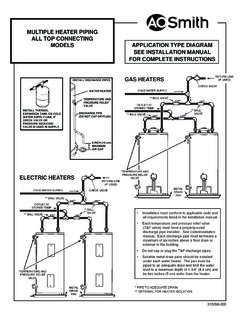
5 (C)11172226333944505661677278 model (Btu/Hr.)Rise (F)2030405060708090100110120130140HW-300 300,000 LPH5,5053,6702,7532,202 1,8351,5731,3761,2231,0011,001918847786 GPH1,45597072758248541636432329126424222 4208HW-399399,000 LPH7,3224,8823,6612,929 2,4412,0921,8311,6271,4641,3311,2201,127 1,046 GPH1,9351,290967774645553484430387352322 298276HW-420420,000 LPH7,7085,1383,8543,083 2,5692,2021,9271,7131,5421,4011,2851,186 1,101 GPH2,0361,3581,0188156795825094534073703 39313291HW-520520,000 LPH9,5436,3624,7713,817 3,1812,7272,3862,1211,9091,7351,5901,468 1,363 GPH2,5211,6811,2611,00884072063056050445 8420388360HW-610610,000 LPH11,194 7,4635,5974,478 3,7313,1982,7992,4882,2392,0351,8661,722 1,599 GPH2,9581,9721,4791,18398684573965759253 849345542344444 CAUTIONTEXT PRINTED OR OUTLINED IN RED CONTAINS INFORMATION RELATIVETO YOUR SAFETY. PLEASE READ THOROUGHLY BEFORE installation diagrams are in this manual. These diagrams will serveto provide the installer with a reference for the materials and method ofpiping suggested.
6 IT IS NECESSARY THAT ALL Water AND GAS PIPINGAND THE ELECTRICAL WIRING BE INSTALLED AND CONNECTED ASSHOWN IN THE THE DIAGRAMS THOROUGHLY BEFORE STARTING INSTALLATIONTO AVOID POSSIBLE ERRORS AND TO MINIMIZE TIME AND design complies with the latest edition of ANSI low-pressure attention should be given to the installation of thermometers atFOREWORDthe locations indicated in the diagrams as these are necessary for checkingthe operation of the SURE THE GAS ON WHICH THE BOILER WILL OPERATE IS THESAME AS THAT SPECIFIED ON THE UNIT RATING boiler installation must conform to these instructions and therequirements of the local authority having required by authority having jurisdiction, the installation must conformto the Standard for Controls and Safety Devices for Automatically FiredBoilers, ANSI/ASME absence of local code requirements, the boiler installation must conformto the National Fuel Gas Code, ANSI and/or CAN/CSA manuals can be purchased from the CSA International, 8501 EastPleasant Valley Road, Cleveland, OH 44131 or 178 Rexdale Boulevard,Toronto, Ontario Canada OF CONTENTSSTART-UP AND OPERATING And and Main Burner.
7 46 Lighting Instructions ..47-48 Pilot and Main Burner (Continued)..49-51 Electronic Intermittent Pilot Ignition Control ..51 Normal Operating Sequence With Honeywell S-8600H orS-8610M Intermittent Ignition Control ( ) ..52 High Altitude Installations ..52 Thermal High Limit Control (Protector Switch)..52-53 Pressure Reducing Valve ..53 Safety Flow Switch ..53-54 Safety Relief Valve OF EXISTING BOILER FROM A COMMONVENTING AND FLUSHING Contaminants ..55 Hot Water Supply Boilers - Preventive Maintenance .. Lime PAGEROUGH-IN DIMENSIONS ..2-3 FOREWORD ..4 INSTALLATION As Boiler Vapor Corrosion ..6 Installation ..6 System 9-11 Gas Pressure 11-12 Venting The Boiler - Standard Maintenance - Standard Venting ..15 Venting Sidewall (Optional) Power Vent System ..15 Venting Relief Valves ..15-16 Wiring Line Temperature Control ..32-33 Low Water ..33 Drain Valve (Not Supplied) ..33 Closed Water INSTRUCTIONSREQUIRED ABILITYINSTALLATION OR SERVICE OF THIS BOILER REQUIRES ABILITYEQUIVALENT TO THAT OF A LICENSED TRADESMAN IN THEFIELD INVOLVED.
8 PLUMBING, AIR SUPPLY, VENTING, GASSUPPLY AND ELECTRICAL WORK ARE AS BOILER REPLACEMENTI nstallation as boiler replacement on an old system with largewater volume may experience condensation within the boiler oncold starts. This condensing of Water vapor in the combustionarea can be prevented if a portion of the system Water flow isdiverted past the boiler to cause an increase in boiler old systems where Water temperature can be expected todrop appreciably due to long standby periods, a bypass pipe of atleast 1" size with a balancing cock should be installed betweenthe boiler inlet and outlet. When the system first starts, the valveshould be slowly opened until the condensing ceases. Thisadjustment remains at a permanent setting to establish requiredtemperature rise across the equipment shall be installed in accordance with thoseinstallation regulations in force in the local area where theinstallation is to be made.
9 These shall be carefully followed in allcases. Authorities having jurisdiction shall be consulted beforeinstallations are installing the boiler, consideration must be given to properlocation. Location selected should be as close to the stack orchimney as practicable with adequate air supply and as centralizedwith the piping system as possible. This location should also besuch that the gas ignition system components are protected fromwater (dripping, spraying, etc.) during appliance operation andservice (circulator replacement, control replacement, etc.).THE BOILER MUST NOT BE INSTALLED ON BOILER SHOULD NOT BE LOCATED IN AN AREA WHERE ITWILL BE SUBJECT TO IT NEAR A FLOOR DRAIN. THE BOILER SHOULD BELOCATED IN AN AREA WHERE LEAKAGE FROM THE BOILER ORCONNECTIONS WILL NOT RESULT IN DAMAGE TO THEADJACENT AREA OR TO LOWER FLOORS OF THE SUCH LOCATIONS CANNOT BE AVOIDED, A SUITABLEDRAIN PAN SHOULD BE INSTALLED UNDER THE BOILER.
10 Suchpans should be fabricated with sides at least 60mm (2-1/2") deep,with length and width at least 50mm (2") greater than the diameterof the boiler and must be piped to an adequate drain. The panmust not restrict combustion air flow. WARNINGKEEPING BOILER AREA CLEAR AND FREE FROM COMBUSTIBLEMATERIALS, GASOLINE AND OTHER FLAMMABLE VAPORS ANDLIQUIDS. WARNINGTHERE IS A RISK IN USING FUEL BURNING APPLIANCES SUCHAS BOILERS IN ROOMS OR AREAS WHERE GASOLINE, OTHERFLAMMABLE LIQUIDS OR ENGINE DRIVEN EQUIPMENT ORVEHICLES ARE STORED, OPERATED OR VAPORS ARE HEAVY AND TRAVEL ALONG THEFLOOR AND MAY BE IGNITED BY THE IGNITER OR MAIN BURNERFLAMES CAUSING FIRE OR EXPLOSION. SOME LOCAL CODESPERMIT OPERATION OF GAS APPLIANCES IF INSTALLED18 INCHES OR MORE ABOVE THE FLOOR. THIS MAY REDUCETHE RISK IF LOCATION IN SUCH AN AREA CANNOT BE AVOIDED. WARNINGFLAMMABLE ITEMS, PRESSURIZED CONTAINERS OR ANYOTHER POTENTIAL FIRE HAZARDOUS ARTICLES MUST NEVERBE PLACED ON OR ADJACENT TO THE BOILER.