Transcription of Model 360/361 Control Valves - Dyna-Flo
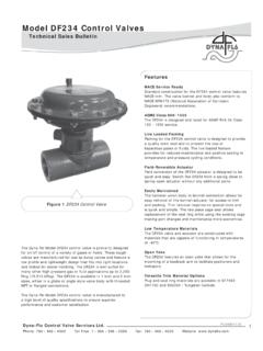
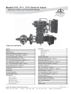
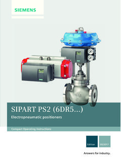
1 Model 360/361 Control ValvesDyna-Flo Control Valve Services Ltd. Phone: 780 469 4000 Toll Free: 1 866 396 2356 Fax: 780 469 4035 Website: P-360M0917B1 Operation, Parts, and Instruction ManualTABLE OF CONTENTSG eneral2 Lapping13 Scope2 Assembly15 Specifi cations3 Stud Installation15 Unpacking5 Plug Seal Assembly15 Installation5 Trim Parts Assembly19 Air Piping6 Bonnet Installation20 Periodic Inspection7 Packing Installation21 Actuator Removal7 Globe Valve Cross Section - Figure 3226 Maintenance8 Angle Valve Cross Section - Figure 3428 Packing Maintenance8 Body to Bonnet Stud Torque - Table 530 Disassembly9 Packing Nut Torque - Table 630 Packing Removal9 Valve Stem Connection Information - Table 730 Bonnet Removal9 Parts31 Trim Parts Removal11 Model Builder49 Packing Parts Removal11 Plug Seal Removal12 Figure 1 360 ControlValve & DFC ActuatorDyna-Flo Control Valve Services Ltd. Phone: 780 469 4000 Toll Free: 1 866 396 2356 Fax: 780 469 4035 Website: Model 360/361 Control ValvesP-360M0917B2 Operation, Parts, and Instruction ManualNOTICE These instructions are meant to be used with the Dyna-Flo 360/361 Technical Bulletin as they refer to Figures and Tables therein.
2 If you do not have the Technical Bulletin, contact Dyna-Flo immediately, or visit Each Control valve is factory checked. Check the calibration for the specifi c application, before a valve is put into service. It is the intention of this document to provide users with an accurate guide for safe installation and maintenance of the 360/361 Control Valves . Revisions are available at above mentioned website. GENERALThe following instructions are to be thoroughly reviewed and understood prior to installing, operating or performing maintenance on this equipment. Work on this equipment should be performed by experienced personnel. Throughout the manual, safety and caution notes appear and must be strictly followed, to prevent serious injury or equipment Control valve confi guration and construction materials were selected to meet particular pressure, temperature, and process conditions. Some material combinations are limited in their pressure and temperature ranges.
3 Do not apply any other conditions to the valve without fi rst contacting your Dyna-Flo sales offi manual is written to be a practical and useful guide to maintaining the Dyna-Flo 360 Control CAUTION Only well trained experienced technicians should perform these procedures. Use safe work practices and lock out procedures when isolating Valves and actuators. It is also important to wear the proper protective equipment when performing any installation or maintenance activity. Use only parts and materials rated for the process being used, operating conditions, and environmental conditions products will be used avoid personal injury or installation damage as a result of the sudden release of process pressure or damage to equipment, do not install the valve assembly where service conditions could exceed the limits stated in this manual, sales bulletin or on the equipment nameplates. Use government codes, accepted industry standards and good piping practices, and select proper pressure-relieving equipment for protection of your installation.
4 Always be aware of fl ammable process and instrument be aware of the hazards of actuators, especially spring-loaded actuators. Be sure that the actuator is de-energized or in the failed position before performing any maintenance procedure. These Valves have dangerous pinch points. Never put your hands inside the valve unless you are certain that the plug and stem will not 360/361 Control ValvesDyna-Flo Control Valve Services Ltd. Phone: 780 469 4000 Toll Free: 1 866 396 2356 Fax: 780 469 4035 Website: P-360M0917B3 Operation, Parts, and Instruction ManualSPECIFICATIONSC onfi gurations The Model 360 Control valve is a high capacity single port, globe style valve with a bolted type bonnet. The standard valve plug action is push down to close. Refer to Table 1. PTFE Seat and Metal Seat Available. Consult your Dyna-Flo sales offi ce for other available confi and Connection Styles (Refer to Table 1) Model : 360 Size: 1 , 1-1/2 , 2 , 3 , 4 , 6 , 8 Body: Globe (All Sizes), Angle (1 / 2 / 3 / 4 / 6 ) Rating: ASME 150 / 300 / 600 Connection: RF / RTJ / BWE - All Sizes SWE / NPT - 1 , 1-1/2 , and 2 Maximum Inlet Pressures and Temperatures Flanged Valves consistent with ASME Class 150, 300, and 600 rating as per ASME , unless Pressure Drops Maximum pressure drop is the same as maximum inlet pressure unless restricted by the following: Standard Valve Trim: Figure 10 of the Sales Bulletin.
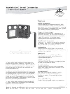
5 Anti-Cavitation Trim: Figure 10 of the Sales Bulletin. Low-Noise Valve Trim: Figure 10 of the Sales Bulletin. Characteristic and Flow Direction Equal Percentage (Standard) - Flow Down Quick Opening - Flow Down Linear - Flow Down Low-Noise 3 (Linear) - Flow Up Anti-Cavitation 1-Stage (Linear) - Flow Down Anti-Cavitation 2-Stage (Linear) - Flow DownDimensions Valve and Actuator Outline Dimension Diagram Refer to Figure 2 of the Sales Bulletin. Valve and Actuator Assembly Dimensions Refer to Tables 8 to 19 of the Sales Bulletin. Approximate Valve Body and Actuator Weights Refer to Table Body and bonnet material options include: LCC (A350 LF2/A105 Dual Grade optional bonnet material) WCC (A350 LF2/A105 Dual Grade optional bonnet material) WC9 (A182 F22 optional bonnet material) CF8M (A182 F316 optional bonnet material) Refer to Figure 10 of the Sales Bulletin for valve construction material temperature limitations. Refer to Table 23 of the Sales Bulletin for trim of the Model 360 Control Valves Refer to Figures 32 to Diameters and Maximum Valve Plug Travel Refer to Tables 4 to 6 of the Sales Type and Examples The Standard packing is PTFE V-ring.
6 Live-loaded low emission, graphite, KALREZ and other packing arrangements are available. Refer to Figures 27, 29, 30, & Valve Sizing Coeffi cients For standard coeffi cients at maximum travel, refer to Table 27 & 28 of the Sales Bulletin. For full list of coeffi cients refer to document Application Refer to Tables 20 - 26 of the Sales more information and other options contact your Dyna-Flo sales offi Control Valve Services Ltd. Phone: 780 469 4000 Toll Free: 1 866 396 2356 Fax: 780 469 4035 Website: Model 360/361 Control ValvesP-360M0917B4 Operation, Parts, and Instruction ManualTable 2 Standard Shut-Off Classifi cations (in accordance with ANSI/FCI and IEC 60534-4)Valve TrimSeat OptionShut-Off ClassAll(Except Anti-Cavitation)PTFE (Soft Seated)StandardClass V (Air Test)OptionalClass VClass VI(1)MetalStandardClass IV OptionalClass V(2)Class VI(1)Anti-Cavitation 1 StageMetal StandardClass IVOptionalClass VAnti-Cavitation 2 StageMetalStandardClass VNotes:1 - Refer to Table - Class V shut-off requires a spring-loaded seal ring, radius-seat plug, and wide-bevel seat ring.
7 Not available with 8 inch ports or quick opening 1 Available Valve Confi gurationsValve ModelValve SizeInchEnd ConnectionNPT(1)RF(2) and RTJ(3) (Flanged)BWE(4)SWE(5)ASME Class 150 ASME Class 300 ASME Class 6003601 / 1-1/2 / 2 3 / 4 / 6 / 8 360A1 & 2 3 / 4 / 6 Notes: 1 - NPT = - RF = Raised - RTJ = Ring Type - BWE = Butt Weld (ASME Class 600 Only).5 - SWE = Socket Weld (ASME Class 600 Only).Table 3 Available Valve Confi gurations for Class VI Shut-Off (in accordance with ANSI / FCI )Valve ModelPort SizeInchValve SeatMinimum Seat Load360 Refer to Table 23 for Trim 7 Metal(1)300 inch 7 PTFEC onsult Dyna-FloNote: 1 - Class VI shut-off requires a spring-loaded seal ring, radius-seat plug, and wide-bevel seat 360/361 Control ValvesDyna-Flo Control Valve Services Ltd. Phone: 780 469 4000 Toll Free: 1 866 396 2356 Fax: 780 469 4035 Website: P-360M0917B5 Operation, Parts, and Instruction ManualUNPACKING VALVE FROM SHIPPING CONTAINERS pecial Tools Required: Properly Rated Lifting Straps (2 4 Straps) refer to Table 4 for actuator weights.
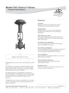
8 Lifting Device (Example: Crane)Check the packing list, verify that the list includes all the materials in the shipping container before unpacking. Valve information can be found on the nameplate (Key 47). Refer toFigure 2 for nameplate lifting the valve from shipping container, place properly rated lifting straps securely around the neck of the actuator, refer to Figure 2 for strap placement. Straps should be placed to avoid damage to tubing and other mounted accessories. For valve assemblies without an attached actuator, use caution when lifting or positioning straps so as not to damage the valve the valve/actuator assembly using proper lifting techniques. INSTALLATIONB efore You Begin: Read the General and Scope section of this manual (Page 2). Read Safety Caution (Page 2). Sudden movement of actuator can cause damage or injury. It helps to have the actuator de-energized. Use safe work practices and lock out procedures before placing valve : For butt weld valve bodies, depending on the body material, post-weld heat treatment might be required.
9 Soft parts, seals, some metal trim, threading and shrink-fi t parts can be damaged by post-weld heat treatment. If post-weld heat treatment is required, it is recommended that all internal valve parts be removed from the valve body. Contact Dyna-Flo for more Required: Appropriate Line Flange Nuts and Bolts Appropriate Line Flange Gaskets If the valve has small internal fl ow passages such as Anti-Cavitation or Low-Noise trim, the installation of an upstream strainer should be considered to prevent clogging of these small 2 Actuator Lifting SuggestionsInstallation Steps:1 Check the packing box bolting (Key 38) for proper tightness. Refer to Packing Installation on Page 20 for proper packing tightening The valve assembly may be installed in any position unless limited by vibration considerations, it is however recommended that the valve be installed with the valve stem (Key 5) perpendicular to the ground. NOTE: For some non-vertical orientations, the valve actuator may need to be Install the valve with fl ow through the valve in the direction shown by the fl ow arrow on the valve Install the appropriate line fl ange Apply Permatex Nickel Anti-Seize to the threads of the fl ange studs and When possible, before tightening the line bolting, stroke the valve and check for smooth operation through the full stroke.
10 Unsteady valve stem movement could be an indication of an internal Tighten the line fl ange bolting in even increments in a crisscross pattern until the correct line bolt torque specifi cation is STRAP47 Dyna-Flo Control Valve Services Ltd. Phone: 780 469 4000 Toll Free: 1 866 396 2356 Fax: 780 469 4035 Website: Model 360/361 Control ValvesP-360M0917B6 Operation, Parts, and Instruction ManualINSTALLATION (Continued)AIR PIPINGWARNING: Property damage, environmental harm, and personal injury can result from the use of supply gas other than clean, non-corrosive, oil and moisture free air. Do not exceed the supply pressure indicated on the serial plate located on the You Begin:Note: Standard actuators accept (6 mm) NPT connections. Refer to the appropriate actuator instruction manual when Installation Steps:1 Use 3/8 (outside diameter) tubing (or equivalent) for air Install the required line vents, Valves , drains, seals, and fi lters to the 4 Valve Body / Actuator Confi gurations and Approximate WeightsValve Size(inch)Body Onlylb (Kg)With Fail OpenActuator SizeValve and ActuatorAssembly Weight lb (Kg)With Fail CloseActuator SizeValve and ActuatorAssembly Weightlb (Kg)130 (14) DFO - 104666 (30)DFC - 104664 (29)DFO - 106970 (32)DFC - 106978 (26)1-1/245 (20)DFO - 104681 (37)DFC - 104679 (36)DFO - 106985 (39)DFC - 106993 (42)285 (39)DFO - 2069136 (62)DFC - 2069135 (61)DFO - 2105167 (76)DFC - 2105175 (79)3125 (57)DFO - 2069176 (80)DFC - 2069175 (79)DFO - 2105207 (94)DFC - 2105215 (98)4170 (77)DFO - 2105252 (114)DFC - 2105260 (118)DFO - 2156277 (126)DFC - 2156291 (132)6350 (159)DFO - 3156466 (211)DFC - 3156471 (214)DFO - 3220585 (266)DFC - 3220604 (274)8900 (408)DFO - 32201135 (515)DFC - 32201154 (523) Model 360/361 Control ValvesDyna-Flo Control Valve Services Ltd.