Transcription of Model 570, 571, 573 Control Valve - Dyna-Flo
1 Model 570, 571, 573 Control ValveDyna-Flo Control Valve Services Ltd. Phone: 780 469 4000 Toll Free: 1 866 396 2356 Fax: 780 469 4035 Website: P-570M1217B1 Operation, Parts, and Instruction ManualTABLE OF CONTENTSG eneral2 Assembly12 Scope2 Bearing Assembly12 Specifi cations3 Ball / Shaft13 Flange Stud Measuring Method - Figure 23 Packing13 Valve Assembly / Dimensions - Figure 34 Ball Seal14570 Valve Dimensions - Table 25 Actuator Mounting14 Mounting Pad Dimensions - Table 45 Packing Ring Installation - Figure 414571 / 573 Valve Dimensions - Tables 3 - 115 Mounting - Figures 5 / 615570 Flange Stud Lengths - Table 86 Mounting Styles and Positions - Table 1216571 / 573 Flange Stud Lengths - Table 97 Follower Shaft Pin Diagram - Figure 716 Flange Stud Diameters - Table 107 Ball Seals - Figure 817 Flange Stud Quantity - Table 117 Ball / Pin Diagrams - Figure 918 Unpacking8 Bearing Driver Tool - Figure 10 / Table 1319 Installation8 Bearing Diagram - Figure 1120 Periodic Inspection9570 Cross Section - Figure 12 and 1321 Packing Maintenance9571 / 573 Cross Section - Figure 1422 Disassembly9 Packing - Figure 1523 Valve / Actuator10 Drive
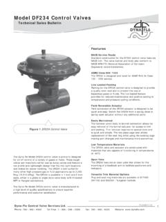
2 Shaft Pin Installation25 Packing Removal10 Follower Shaft Pin Installation26 Ball Seal Removal10 Ball / Shaft Assembly27 Ball / Shaft / Bearings11 Parts28 Bearing Removal12 Model Builder36 Dyna-Flo Control Valve Services Ltd. Phone: 780 469 4000 Toll Free: 1 866 396 2356 Fax: 780 469 4035 Website: Model 570, 571, 573 Control ValveP-570M1217B2 Operation, Parts, and Instruction ManualNOTICE These instructions are meant to be used with the Dyna-Flo 570 Series Technical Bulletin as they refer to Figures and Tables therein. If you do not have the Technical Bulletin, contact Dyna-Flo immediately, or visit Each Control Valve is factory checked. Check the calibration for the specifi c application, before a Valve is put into service. It is the intention of this document to provide users with an accurate guide for safe installation and maintenance of the 570 Series Control valves .
3 Revisions and updates are available at above mentioned website. GENERALThe following instructions are to be thoroughly reviewed and understood prior to installing, operating or performing maintenance on this equipment. Work on this equipment should be performed by experienced personnel. Throughout the manual, safety and caution notes appear and must be strictly followed, to prevent serious injury or equipment Control Valve confi guration and construction materials were selected to meet particular pressure, temperature, and process conditions. Some material combinations are limited in their pressure and temperature ranges. Do not apply any other conditions to the Valve without fi rst contacting your Dyna-Flo sales offi manual is written to be a practical and useful guide maintaining the Dyna-Flo 570 Series Control To avoid personal injury or installation damage as a result of the sudden release of process pressure or the breaking of parts, do not install the Valve assembly where service conditions could exceed the limits stated in this manual or on the equipment nameplates.
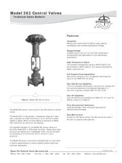
4 Use government codes, accepted industry standards and good piping practices to select pressure-relieving equipment for protection of your installation. It is also important to wear the properprotective equipment when performing any installation or maintenance 1 Available Valve Confi gurationsValve ModelEnd ConnectionBody MaterialValve SizeinchValve Rating570 FlangelessMates with ASME Class 150/300/600 Raised Face FlangesLCCCG8M1 / 1-1/2 / 2 ASME Class 150/300/6003 & 4 ASME Class 150 ASME Class 300/6006 & 8 ASME Class 150/300/600571 FlangedMates with ASME Class 150 Raised Face FlangesLCC / WCC / CG8M 1 / 1-1/2 / 2 / 3 / 4 / 6 / 8 / 10 / 12 ASME Class 150573 FlangedMates with ASME Class 300 Raised Face FlangesLCC / WCC / CG8M 1 / 1-1/2 / 2 / 3 / 4 / 6 / 8 / 10 / 12 ASME Class 300 Model 570, 571, 573 Control ValveDyna-Flo Control Valve Services Ltd. Phone: 780 469 4000 Toll Free: 1 866 396 2356 Fax: 780 469 4035 Website: P-570M1217B3 Operation, Parts, and Instruction ManualMEASURE FROM FIRST FULL THREAD TO FIRST FULL THREADF igure 2 Flange Stud MeasuringMethodSPECIFICATIONSM aximum Pressure / Temperature Ratings Consistent with applicable pressure / temperature ratings per ASME Refer to Tables 16 & 17 of Sales Allowable Shutoff Pressure Drop Refer to Table 17 of Sales Bulletin.
5 750 Psig (5,171 kPag) @ 100oF (38oC) (Standard Construction)Material Temperature Capabilities Valve Body: Standard: -50oF to 450oF (-46oC to 232oC) LCC Optional: High Temp -20oF to 800oF (-29oC to 427oC) WCC Packing: PTFE: -50oF to 450oF (-46oC to 232oC) Graphite: -325oF to 1000oF (-198oC to 538oC) Live Loaded PTFE: -50oF to 450oF (-46oC to 232oC) (for 100 ppm service requirements) Live Loaded Graphite: 20oF to 600oF (-7oC to 316oC) (for 100 ppm service requirements) 20oF to 700oF (-7oC to 371oC) (for non-environmental service requirements) Refer to Tables 16 & 17 of Sales Materials Refer to Parts for construction materials. Contact your Dyna-Flo sales offi ce for more information and other Direction Forward (through seal into ball).Actuator Mounting Right-hand, or Left-hand (as viewed from seal end of Valve ). In one of 4 positions (12 (Std.), 3, 6, and 9 o clock) with respect to the Valve body in a horizontal Ball Rotation 90 Classifi cation Composition Ball Seal: Class VI Metal Ball Seal: Class IV Classes and testing per ANSI/FCI 70-2 and IEC 60534-4.
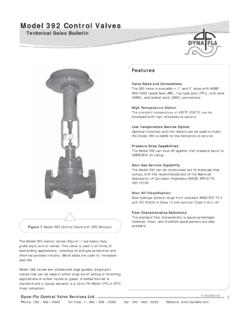
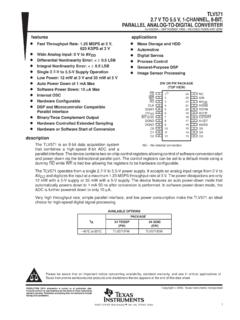
6 Tested at the service pressure drop, or 50 Psig (345 kPag), whichever is lower Valve Dimensions Refer to Figures 2 & 3 for Valve diagram. Refer to Tables 2 - 11 for Valve dimensions. Refer to Tables 8, 9, 10, & 11 for bolting and Actuator Assembly Weight Refer to Table 2 of Sales Line Flange Bolting - Tables 8, 9, 10, & 11. Stainless Steel Construction. Internal Coatings. Shaft Connections: - Splined (Standard) - Square (Optional - 1 to 6 valves ) - Keyed (Optional - 8 to 12 valves )For more information and other options contact your Dyna-Flo sales offi Control Valve Services Ltd. Phone: 780 469 4000 Toll Free: 1 866 396 2356 Fax: 780 469 4035 Website: Model 570, 571, 573 Control ValveP-570M1217B4 Operation, Parts, and Instruction ManualFigure 3 Typical Valve Assembly Diagram and DimensionsAMODEL 571 & 573 LKMODEL 570 IMMONN1 - 2 VALVE3 to12 VALVESJSSPLINED SHAFTJSQ Q (SQUARE)P1 - 6 VALVESSQUARE SHAFTDETAILJSTUW8 - 12 Valve KEYED SHAFT DETAIL8 - 12 Valve KEYED SHAFT DETAILC entering Studs323232 Model 570, 571, 573 Control ValveDyna-Flo Control Valve Services Ltd.
7 Phone: 780 469 4000 Toll Free: 1 866 396 2356 Fax: 780 469 4035 Website: P-570M1217B5 Operation, Parts, and Instruction ManualTable 3 Model 571 and 573 Valve Dimensions Inch (mm) Valve / ActuatorSizeDimensional ReferenceA1 / (102)1-1/2 / (114)2 / (124)3 / (165)4 / (194)6 / (229)8 / (243)8 / (243)10 / (297)12 / (338)ASME Class: 571 = 150, 573 = 300 Envelope Dimensions are + / - in. ( mm) Face to Face Tolerance Per ASMET able 2 Model 570 Valve Dimensions Inch (mm) Valve / ActuatorSizeDimensional ReferenceA1 / (102)1-1/2 / (114)2 / (124)3 / (165)4 / (194)6 / (229)8 / (243)8 / (243)ASME Class: 150 / 300 / 600 Envelope Dimensions are + / - in. ( mm) Face to Face Tolerance Per ASMET able 4 Valve Mounting Pad Dimensions Inch (mm) - Refer to Figure SizeInchDimensional ReferenceNMO1 / 1-1/2 / ( ) (117) 3 / 4 / ( ) (152) ( )8 / 10 / ( ) (235) ( )Table 5 Model 570, 571, and 573 Square Shaft Dimensions Inch (mm) - Refer to Figure SizeInchDimensional ReferenceJSPQ1 Consult Dyna-FloConsult Dyna-FloConsult Dyna-FloConsult Dyna-Flo1-1/2 Consult Dyna-FloConsult Dyna-FloConsult Dyna-FloConsult ( )5/8 X 1/2 ( X ) ( ) ( ) ( )3/4 ( ) ( ) ( ) ( )3/4 ( ) ( ) ( ) ( )1 ( ) ( ) ( ) Dyna-Flo Control Valve Services Ltd.
8 Phone: 780 469 4000 Toll Free: 1 866 396 2356 Fax: 780 469 4035 Website: Model 570, 571, 573 Control ValveP-570M1217B6 Operation, Parts, and Instruction ManualTable 6 Model 570, 571, and 573 Splined Shaft Dimensions Inch (mm) - Refer to Figure (188)1/2 ( ) (188) (188) (188) (188)1-1 (188)5/8 X 1/2 ( X ) (188)5/8 X 1/2 ( X ) (188)5/8 X 1/2 ( X ) (188)5/8 X 1/2 ( X ) (188)5/8 X 1/2 ( X ) (188)5/8 X 1/2 ( X ) (214)3/4 ( ) (214)3/4 ( ) (214)3/4 ( ) (214)3/4 ( ) (214)3/4 ( ) (214)3/4 ( ) (214)1 ( ) (214)1 ( ) (214)1 ( ) (208)1-1/4 ( ) (208)1-1/4 ( ) (208)1-1/4 ( )10 (208)1-1/4 ( ) (208)1-1/4 ( )12 (208)1-1/2 ( ) (208)1-1/2 ( )Table 7 Model 570, 571, and 573 Keyed Shaft Dimensions Inch (mm) - Refer to Figure SizeInch570571 & ( )1-1/4 ( ) ( )1-1/8( ) ( ) ( )1-1/4 ( ) ( )1-1/8( ) ( )8 Valve Shafts use a 1/4 x Key ( )1-1/4 ( ) ( )1-1/8( ) ( )10 Valve Shafts use a 1/4 x Key ( )1-1/2 ( ) ( )1-3/8( ) ( )
9 12 Valve Shafts use a 5/16 x Key 8 Model 570 Line Flange Stud Lengths Inch (mm) - Refer to Figures 2 & SizeInchIClass 150 Class 300 Class 6001 (176) (202) (202)1-1 (189) (224) (224) (211) (237) (237) (254) (286) (286) (286) (343) (343) (343) (362) (413) (343) (387) (426) Model 570, 571, 573 Control ValveDyna-Flo Control Valve Services Ltd. Phone: 780 469 4000 Toll Free: 1 866 396 2356 Fax: 780 469 4035 Website: P-570M1217B7 Operation, Parts, and Instruction ManualTable 9 Model 571 and 573 Flange Stud Lengths Inch (mm) - Refer to Figures 2 & (73) (79) (94) (100)1-1 (80) (92) (108) (114) (87) (100) (100) (106) (100) (106) (121) (133) (100) (119) (127) (140) (114) (127) (140) (152) (127) (133) (152) (165) (133) (146) (173) (186) (133) (152) (186) (198)Table 10 Flange Stud Diameters and Threads Per Inch (TPI) Valve SizeInchTPIC lass 150 Class 300 Class 6001 Consult Dyna-FloConsult Dyna-FloConsult Dyna-Flo1-1/2 Consult Dyna-FloConsult Dyna-FloConsult Dyna-Flo25/8 - 115/8 - 115/8 - 1135/8 - 113/4 - 103/4 - 1045/8 - 113/4 - 107/8 - 963/4 - 103/4 - 101 - 883/4 - 107/8 - 91-1/8 - 810 (571 & 573 ONLY)7/8 - 91 - 8N/A12 (571 & 573 ONLY)7/8 - 91-1/8 - 8N/ATable 11 Flange Stud QuantityValve SizeInchNumber of Studs Required (Double for Models 571 & 573)
10 Class 150 Class 300 Class 6001 / 1-1/2 / 2 / 3488488868121288121210 (571 & 573 ONLY)1216N/A12 (571 & 573 ONLY)1212N/ADyna-Flo Control Valve Services Ltd. Phone: 780 469 4000 Toll Free: 1 866 396 2356 Fax: 780 469 4035 Website: Model 570, 571, 573 Control ValveP-570M1217B8 Operation, Parts, and Instruction ManualUNPACKING Valve FROM SHIPPING CONTAINERC heck the packing list against materials received, while unpacking the Valve . The Packing List describes Valve and accessories in each shipping preparing valves and actuators for lifting, be sure to use certifi ed lifting equipment and proper rigging. Position anylifting straps to avoid damage to the tubing and mounted Refer to the General and Scope sections of this Manual (See Page 2) prior to beginning installing these valves , be sure to inspect the fl ange mating surfaces on both the Valve and the pipeline fl anges. Clean dirt, welding chips, scale or other foreign material from the line and fl ange surfaces.