Transcription of Model 5000 Level Controller - Dyna-Flo
1 Model 5000 Level ControllerDyna-Flo Control Valve Services Ltd. Phone: 780 469 4000 Toll Free: 1 866 396 2356 Fax: 780 469 4035 Website: P-5000B0416A1 Technical Sales BulletinFeaturesMultiple Confi gurationsThe 5000 Level Controller is easily confi gured for either reverse or direct actions for both pneumatic and electric pilot options. The pneumatic pilot is available in snap acting and throttling designs. The displacer can be easily changed from vertical to horizontal without any , Durable and SimpleOur Model 5000 has proven that it will outperform in demanding applications.
2 The simple design lends itself to these rugged environments and the familiar adjustability makes tuning seamless. Powder coated case for outstanding resistance to weather and Reversible Confi gurationThe output of the 5000 Controller can be fi eld adjusted to be reverse or direct acting without additional parts. Also, this Controller features adjustable gain Bleed RelayThe 5000 Controller does not bleed supply gas duringsteady state operation, this helps reduce harmful emissions and lowers operating ServiceStandard construction materials comply with therecommendations of (NACE)
3 National Association of Corrosion Engineers Pressure RatingThe vessel connection components are designed and rated for ASME Class 1500 , Vented CaseStandard sealed doors facilitate the use of fl ammable supply gases allowing these gases to be vented through tubing to a remote MaintenanceThis Model supports effi cient access to all internalcomponents for easy inspection and maintenance. Seals can be replaced without disrupting the vessel Back MountingVersatile back mount design suits all mounting Dyna-Flo 5000 series Level controllers are implemented for use in many demanding applications, including oil and gas production and chemical process industries.
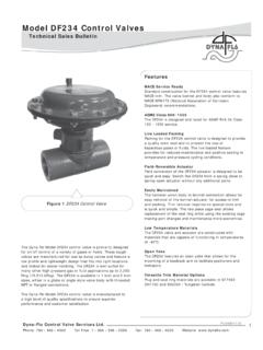
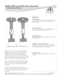
4 Typical applications would be on gas scrubbers and separators, where liquid Level control is required as well as natural gas compressors and process control 5000 Level Controller (Figure 1) utilizes an innovative relay manifold design providing easy maintenance and greater safety. The Controller provides a pneumatic signal output for use with a control valve. The design allows for operational consistency through high and low pressure applications. Incorporated into the 5000 controllers design is unique access to the seal around the displacer arm, making maintenance Dyna-Flo 5000 series Level controllers are manufactured to a superior Level of quality and design to ensure impeccable performance and customer 1 Model 5000 Level ControllerDyna-Flo Control Valve Services Ltd.
5 Phone: 780 469 4000 Toll Free: 1 866 396 2356 Fax: 780 469 4035 Website: Model 5000 Level ControllerP-5000B0416 ASPECIFICATIONSC onfi gurations Controllers Throttling Snap-acting Sensors Pivotal movement of displacer arm is transmitted to the Controller by a displacer-style liquid Level sensor mounted to the side of Displacer Size 1-7/8 x 12 inches, 33 inches3 (48 x 305 mm, 541 cm3).Minimum Specifi c Gravity Snap-Acting Controller Minimum specifi c gravity (specifi c gravity differential for interface applications) Throttling Controller Minimum specifi c gravity (specifi c gravity differential for interface applications) Pneumatic (standard) Snap (on/off) 0-20 / 0-30 psig output Throttle (modulating) 3-15 / 6-30 psig output Electric (optional)
6 SPDT - Explosion Proof DPDT - Explosion ProofSupply Pressure Requirements Snap-Acting Controller 3-15 or 0-20 Psig output: 20-30 Psig min. 6-30 or 0-30 Psig output: 35-40 Psig min. NOTE - Do Not Use Supply Pressure Below 20 Psig (138 kPag).2 Technical Sales BulletinEnd ConnectionMaximum Pressure Ratingat 38oC (100oF)MNPT3,750 Psig (25,855 kPag)150 RF285 Psig (1,965 kPag)300 RF740 Psig (5,102 kPag)600 RF1,480 Psig (10,204 kPag)600 RTJ1,480 Psig (10,204 kPag)900 RF2,220 Psig (15,306 kPag)900 RTJ2,220 Psig (15,306 kPag)1500 RF3,750 Psig (25,855 kPag)1500 RTJ3,750 Psig (25,855 kPag)Maximum Sensor Operating Pressure Conforming with Class 1500 pressure temperature ratings per ASME up to maximum pressure of 3,750 Psig (25,855 kPag)
7 Maximum Displacer Operating Pressure 3,750 Psig (25,855 kPag).Standard Pressure Gauge Indications (Supply and Output) Triple scale gauges in 0 to 60 Psig / 0 to MPa / 0 to 2,758 Connections Output 1/4 inch NPT female located on back of case. Supply 1/4 inch NPT female located on the back of case. Case Vent 1/4 inch NPT located on bottom of case, vent screen apparatus to Sensor Connection 1-1/2 , 2 , 3 , and 4 threaded (NPT) or fl Temperature Limits PVC Displacer -29 to 80oC (-20 to 175oF).
8 HSN (Highly Saturated Nitrile) O-Rings -40 to 204oC (-40 to 400oF). Viton O-Rings -26 to 204oC (-15 to 400oF). 316 SST Displacer Non-limiting. Operative Ambient Temperature Limits For Controller : -29 to 204oC (-20 to 400oF) Model 5000 Level ControllerDyna-Flo Control Valve Services Ltd. Phone: 780 469 4000 Toll Free: 1 866 396 2356 Fax: 780 469 4035 Website: P-5000B0416A3 Technical Sales BulletinSPECIFICATIONS - Electric Pilot Output - proportional band adjustment SPDT (single pole double throw) 7 - 55% DPDT (double pole double throw) 20 - 150%Switch Rating UL and CSA listed: L96 15 amps, 125, 250, or 480 1/8 Hp, 125 ; 1/4 Hp, 250 1/2 amp, 125.
9 1/4 amp, 250 Rating -40 to 71OC (-40 to 160OF)Electric Pilot Model Number SPDT (single pole double throw) EX-Q DPDT (double pole double throw) EXD-QCertifi cations Approvals: UL, CSA, ATEX (CE), IEC EX Designations: Div. 1 & 2, Class l, Groups B, C, & D Div. 1 & 2, Class ll, Groups E, F, & G ll 2 G; EEX d llB + H2 T6 ELECTRIC PILOT GENERAL INFORMATION The fl ame paths of Honeywell s EX explosion-proof switches cool exploding gases below the ignitiontemperature before they reach explosive gases surrounding the housing.
10 The enclosed replaceable basic switch is accessible when the cover is removed. EX series products are NEMA 1 rated and therefore are not recommended for use in areas when they will be subjected to liquid series products are listed by Underwriters Laboratories and CSA for use in hazardous locations NEMA 7, Class I, Groups C & D, and NEMA 9, Class II, Group E, F, and G. This includes vapors of ethyl ether, gasoline, petroleum, alcohol, acetone, lacquer solvent, natural gas, and atmospheres charged with grain dust, metal dust, carbon black, coal, or coke dust.