Transcription of Model DFC and DFO Valve Actuator - Dyna-Flo
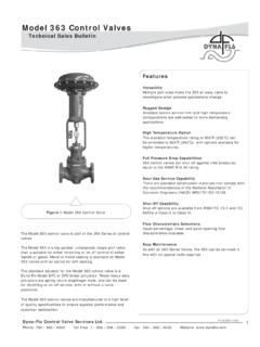
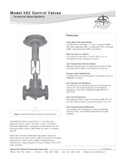
1 Model DFC and DFO Valve ActuatorDyna-Flo Control Valve Services Ltd. Phone: 780 469 4000 Toll Free: 1 866 396 2356 Fax: 780 469 4035 Website: P-DFCOB1019A1 Technical Sales BulletinThe Model DFC and DFO series linear output spring and diaphragm actuators are used in all kinds of demandingapplications. The large area of the diaphragm allows low-pressure operation, and the spring provides fail safe positioning of a control Valve on loss of the pneumatic Model DFC and DFO are used to automate control valves in both throttling and on/off control of liquids or combined with a Dyna-Flo Model DF2000 or 360 Valve ,the DFC or DFO is part of a rugged control Valve assembly.
2 To which a wide variety of controllers and instruments can be s high level of quality specifi cations used in manufacturing the Model DFC and DFO series linear pneumatic actuators ensures superior performance and customer 1 Models DFC and DFO ActuatorsFeaturesReliable DesignFormed diaphragm has no friction with other moving parts allowing maintenance free operation through years of constant CoatingsExternal surfaces are either epoxy or powder coated for optimum resistance to harsh TestedEach Actuator receives extensive testing to confi rm smooth leak free for Instrument MountingIntegrated mounting pads with threaded holes make easy work of mounting instruments to the Actuator .
3 The open yoke allows easy access to stems for feed IndicationHighly visible travel scale is adjustable for precise position Control Valve Services Ltd. Phone: 780 469 4000 Toll Free: 1 866 396 2356 Fax: 780 469 4035 Website: Model DFC and DFO Valve ActuatorP-DFCOB1019 ASPECIFICATIONSM aterial Temperature Capabilities Standard: -40 to 180 oF (-40 to 82 oC)Construction Materials Refer to Tables 15-18 for construction details. Contact your Dyna-Flo sales offi ce for more information and other Stem Compatibility, inches (mm) 1046, 1069 3/8 ( ) 2069, 2105, 2156 1/2 ( ) 3105, 3156, 3220, 3220-4 3/4 (19) Valve Mounting Connection Sizes, inches (mm) 1046, 1069 2-1/8 (54) 2069, 2105, 2156 2-13/16 (71) 3105, 3156, 3220, 3220-4 3-9/16 (90) Actuator Weights, lb (kg)Line Connection Size All sizes, 1/4 inch FNPT, other sizes Mounting Vertical on Valve yoke 360o rotatable for optimum accessory Dimensions Refer to Figures 2-6 for Actuator diagram.
4 Refer to Tables 10-14 for Actuator Reduced travel output Increased tubing connection size Stem connections Mechanical Travel stops Corrosion resistant materials2 Technical Sales BulletinOperationThe Model DFC spring return diaphragm Actuator (Figure 7) employs time proven reliable technology. As the instrument signal to the sealed lower diaphragm casing is increased, the force generated by that pressure on the diaphragm, and diaphragm plate, force the diaphragm plate and Actuator stem up, compressing the spring. The lifting action is transferred to the Valve stem through a secure split and bolted connecting block. On a decrease, or complete loss of pneumatic signal, the Actuator spring will force the Actuator stem to extend, putting the Valve in its fail-safe position.
5 Using a push down to close action Valve with a Model DFC will result in a fail closed Valve assembly. The Model DFO spring return diaphragm Actuator is also time proven. Refer to Figure 8. As the instrument signal to the sealed upper diaphragm casing is increased, the force generated by that pressure on the diaphragm, and diaphragm plate, force the diaphragm plate and Actuator stem down, compressing the spring. The extension action is transferred to the Valve stem through a secure split and bolted connecting block. On a decrease, or complete loss of pneumatic signal, the Actuator spring will force the Actuator stem to retract, putting the Valve in its fail-safe position. Using a push down to close action Valve with a Model DFO will result in a fail open Valve (Figures 9, 10, 13, 14)Top-mounted handwheels are the cost effective option available for manual override for DFC and DFO actuators.
6 The top-mounted handwheel is a good choice for emergency only positioning of a Valve , and it is commonly used as a travel stop. These top-mounted handwheels are available in all Actuator sizes. Side-mounted handwheels are also Travel Stops (Figures 11 & 12)Top mounted handwheel based travel stops are available to restrict Valve opening or closing. Confi gurations are available with caps to reduce (15)36 (16)1069 48 (22)40 (18)206950 (23)51 (23)210590 (41)82 (37)2156 121 (55)107 (49)310594 (43)92 (42)3156 122 (55)116 (53)3220254 (115)235 (107)3220-4274 (124)255 (116) Model DFC and DFO Valve ActuatorDyna-Flo Control Valve Services Ltd. Phone: 780 469 4000 Toll Free: 1 866 396 2356 Fax: 780 469 4035 Website.
7 P-DFCOB1019 ATable 1 Volumetric Casing Displacement Inch3 (cm3) Actuator SizeClearanceVolume(ZeroTravel)Travel Inch (mm)7/16 (11)5/8 (16)3/4 (19)1-1/8 (29)1-1/2 (38)2 (51)3 (76)4 (102)104633 (540)56 (918)66 (1080)72 (1180)---------------106957 (934)90 (1470)104 (1700)113 (1850)142 (2330) 170 (2790)---------206957 (934)90 (1470)104 (1700)113 (1850)142 (2330) 170 (2790)---------210595 (1560)---170 (2790)183 (3000)227 (3720) 270 (4420) 330 (5410)------2156133 (2180)---237 (3880)257 (4210)322 (5280) 387 (6340) 472 (7740)------310595 (1560)---170 (2790)183 (3000)227 (3720) 270 (4420) 330 (5410)------3156133 (2180)---237 (3880)257 (4210)322 (5280) 387 (6340) 472 (7740)------3220213 (3490)320 (5240) 363 (5950)392 (6420)478 (7830) 564 (9240)678 (11110)980 (14880)---3220-4213 (3490)320 (5240) 363 (5950)392 (6420)478 (7830) 564 (9240)678 (11110)980 (14880)1133 (18570)3 Technical Sales BulletinDyna-Flo Control Valve Services Ltd.
8 Phone: 780 469 4000 Toll Free: 1 866 396 2356 Fax: 780 469 4035 Website: Model DFC and DFO Valve ActuatorP-DFCOB1019A4 Technical Sales BulletinTable 2 Model DFC Actuator Specifi cationsSPECIFICATIONACTUATOR SIZE10461069206921052156310531563220(1)N ominal Effective Areainch2466969105156105156220cm22974454 45667100667710061419 Yoke Boss Diameterinch2-1/82-1/82-13/162-13/162-13 /163-9/163-9/163-9/16mm5454717171909090 Acceptable Valve Stem Diameterinch3/83/81/21/21/23/43/43 Allowable Output Thrustlb2,3002,3002,7005,6507,5505,6506, 8008,800N10,23010,23012,01025,13133,5822 5,13130,24639,142 Maximum Travel(2)Standardinch3/41-1/81-1/222223( 3)mm1929385151515176 Top-Loadedinch---3/4---3/4------1-1/8--- mm---19---19------29---Maximum Casing Pressure for Actuator Sizing(4,5)Psig5570706555655550kPag38048 3483448379448379345 Maximum Excess Diaphragm Pressure(4)Psig5520201010101010kPag38013 81386969696969 Maximum Diaphragm Casing Pressure(4,5)Psig11090907565756560kPag76 0621621517448517448414 MaterialTemperatureCapabilitiesNitrile Elastomers-40 to 180oF (-40 to 82oC)Silicone Elastomers-40 to 300oF (-40 to 149oC)NOTES:1 These values also apply to the DFC Size 3220-4 Actuator travel may be less than the value listed after connected to the Maximum Actuator travel for the 3220-4 is 4 inches (102 mm).
9 4 Additional pressure may be added to the Actuator when the Actuator is at full travel. Damage to the Actuator will occur if the Maximum Excess Diaphragm Pressure is exceeded. When the Actuator has reached its full travel, and the diaphragm plate is physically stopped from moving, the energy from additional pressure is transferred to the diaphragm and casing. The amount of excess pressure that can be added at full travel is limited, exceeding this limiting factor will result in damage to the Actuator , leakage, and/or casing fatigue or This Maximum Casing Pressure is not to be used for normal operating pressure. Its purpose is to allow for typical regulator supply settings and/or relief Valve tolerances.
10 The maximum casing pressure is the pressure that can be applied to the Actuator when the Actuator is at less than full travel. Damage to the Actuator may occur if this pressure is exceeded before the full travel is DFC and DFO Valve ActuatorDyna-Flo Control Valve Services Ltd. Phone: 780 469 4000 Toll Free: 1 866 396 2356 Fax: 780 469 4035 Website: P-DFCOB1019A5 Technical Sales BulletinTable 3 Model DFO Actuator Specifi cationsSPECIFICATIONACTUATOR SIZE10461069206921052156310531563220(1)N ominal Effective Areainch2466969105156105156220cm22974454 45677100667710061419 Yoke Boss Diameterinch2-1/82-1/82-13/16 2-13/16 2-13/163-9-163-9/163-9/16mm5454717171909 090 Acceptable Valve Stem Diameterinch3/83/81/21/21/23/43/43 Allowable Output Thrustlb23002300270056507550565068008800 N10,23110,23112,01025,13233,58425,13230, 24839,144 Maximum Travel(2)inch3/41-1/81-1/222223(3)mm1929 385151515176 Maximum Casing Pressure for Actuator Sizing(4)Psig12565655040504055kPag862448 448345276345276379 Maximum Diaphragm Casing Pressure(4,5)