Transcription of INSTALLATION AND F.A.Q.’s - Dyna-Flo
1 SIEMENS PS2 INSTALLATION AND ssliding stem and rotary applicationsDyna-Flo Control Valve Services Ltd. Phone: 780 469 4000 | Toll Free: 1 866 396 2356 | P-PS2Q0619A1 Our Commitment to QualityDyna-Flo is committed to continuous improvement. While all efforts have been made to ensure the accuracy of the content in this document, modifi cations or improvements to the information, specifi cations, and designs may occur at any time without notice. This document was published for informational purposes only, and does not express or imply suitability, a warranty, or guarantee regarding the products or services described herein or their use or applicability. Neither Dyna-Flo Control Valve Services Ltd., nor any of their affi liated entities assumes responsibility for the selection, use and maintenance of any product. Responsibility for selection, use and maintenance of any product remains with the purchaser and Control Valve Services Ltd.
2 Phone: 780 469 4000 | Toll Free: 1 866 396 2356 | P-PS2Q0619 ATABLE OF CONTENTSCONTENTPAGEM ounting Instructions3-20 Old Style Basic Linear Actuator Mounting Instructions3 Old Style Basic Linear Actuator Mounting Diagram4 New Style Basic Linear Actuator Mounting Instructions8 New Style Basic Linear Actuator Mounting Diagram13 Basic Rotary Actuator Mounting Instructions15 Basic Rotary Actuator Mounting Diagram16 Quarter Turn Rotary Actuator Mounting Instructions19 Quarter Turn Rotary Actuator Mounting Diagram20 Siemens Overview for Factory Mounted PS2 s21-22 Display Window21 Operation Keys21 Modes of Operation21 Automatic21 Manual22 Confi guration22 Diagnostic22 Positioner Setup and Calibration23-26 Clearing the Memory26 Operations and Confi gurations27-30 Charts and Diagrams29 Parameters Chart31-32 Functional Upgrade33-35 Procedure33 Diagram34-35 FAQ / Troubleshooting and Solutions36-38 Valve Is Not Actuating36PS2 Positioner Is Hunting36PS2
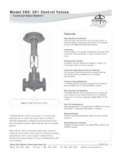
3 Positioner Does Not Move Valve36PS2 Positioner Is Constantly Venting36 There Is Power and 4-20 mA But No Display36 Valve Is Being Moved In Wrong Direction37 Power Interruption / Broken Connection37 Positioner Goes Past Closed To A Negative Value37 Valve Does Not Fully Open Or Close37 Valve Actuates Too Quickly372 Dyna-Flo Control Valve Services Ltd. Phone: 780 469 4000 | Toll Free: 1 866 396 2356 | P-PS2Q0619 ATools Required: Wrenches (5/16 , 3/8 , 7/16 , 1/2 9/16 , 10 mm, and 13mm) Slotted Screwdriver Phillips Screwdriver Terminating Screwdriver Hex Wrench SetFor linear valves, mount all hardware as shown in Figure determine which holes on the mounting bracket to use, refer to Figures 2 & 3 and Table 2 or follow these steps:1 Set the actuator at half Align the feedback loop (Key 5) and feedback arm (Key 4) so that they are both horizontal, as shown in Figure The feedback loop (Key 5) should be compressing the spring on the feedback arm assembly (Key 4) anywhere between 1/4 and 1/2.
4 NOTE: In order to achieve proper spring compression it may be necessary to fl ip the mounting bracket - connecting block (Key 2).4 Depending on the actuator type, size, and travel, a different combination of holes on the mounting bracket will have to be used for each application. The top 5 rows of holes are used to mount to the actuator. The bottom 4 rows are used to mount to the positioner. Choose the combination that best allows the feedback arm (Key 4), and the feedback loop (Key 5) to be horizontal and parallel at half Once this arrangement is set, tighten all the Follow start-up as described in this handbook or in the Chapter on Commissioning of the Siemens SIPART PS2 Operating instructions (Latest Edition).OLD LINEAR MOUNTING INSTRUCTIONS3 Dyna-Flo Control Valve Services Ltd. Phone: 780 469 4000 | Toll Free: 1 866 396 2356 | P-PS2Q0619 AFigure 1 Linear Hardware Mounting Diagram10113123768152549 OLD LINEAR MOUNTING INSTRUCTIONS4 Dyna-Flo Control Valve Services Ltd.
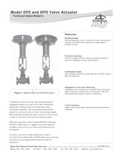
5 Phone: 780 469 4000 | Toll Free: 1 866 396 2356 | P-PS2Q0619 ATable 1 Linear Actuator Mounting Parts ListKeyDescriptionQuantity1 Bracket, Yoke - Sliding Stem12 Mounting Bracket - Connecting Block13 Adjusting Bracket - Feedback Loop14 Feedback Arm Assembly15 Feedback Loop16 Washer - Feedback Loop17 Hex Nut48 Hex Cap Screw, Adjusting Bracket - Mounting29 Lock-washer410 Hex Cap Screw, Mounting Bracket - Positioner211 Lock-washer, Mounting Bracket - Yoke (Not Shown)212 Hex Cap Screw, Mounting Bracket - Positioner413 Lock-washer, Mounting Bracket - Positioner414 Airset Mounting Screw (Not Shown)215 Hex Cap Screw - Connecting Block(Not Included - Use Existing Cap Screws)216 Airset Regulator (Not Shown)117 Spacer, Mounting Bracket - Yoke(Not Shown - Sizes 1046, 1069, & 2069 Only)2 For Mounting instructions refer to Pages 2, 7, & LINEAR MOUNTING INSTRUCTIONS5 Dyna-Flo Control Valve Services Ltd. Phone: 780 469 4000 | Toll Free: 1 866 396 2356 | P-PS2Q0619 AOLD LINEAR MOUNTING INSTRUCTIONS234B51A23541 AFigure 2 Mounting Bracket Mounting Hole DiagramFigure 3 Mounting Bracket DFO Size 3220 Mounting Hole Diagram6 Dyna-Flo Control Valve Services Ltd.
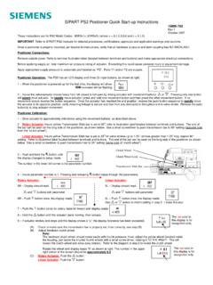
6 Phone: 780 469 4000 | Toll Free: 1 866 396 2356 | P-PS2Q0619 ATable 2 Actuator Mounting Bracket Mounting Hole Location ChartACTUATOR SIZETRAVELHOLE PATTERNACTUATOR SIZETRAVELHOLE PATTERNDFC 10463/4 5-BDFO 10463/4 5-ADFC 10693/4 4-ADFO 10693/4 4-A1-1/8 4-A1 4-ADFC 20693/4 5-ADFO 20693/4 4-A1-1/8 5-A1-1/8 4-A1-1/2 5-A1-1/2 3-ADFC 2105 DFC 21563/4 1-ADFO 2105 DFO 21563/4 3-A1-1/8 1-A1-1/8 3-A1-1/2 1-A1-1/2 3-A2 2-A2 2-ADFC 3105 DFC 31563/4 2-ADFO 3105 DFO 31563/4 3-A1-1/8 2-A1-1/8 3-A1-1/2 3-A1-1/2 3-A2 3-A2 2-ADFC 32203/4 2-ADFO 32203/4 4-A1-1/8 2-A1-1/8 4-A1-1/2 2-A1-1/2 4-A2 3-A2 4-A3 2-A3 4-ADFC 3220-42 4-ADFO 3220-42 NA*2-1/2 4-A2-1/2 NA*3 4-A3 5-A4 4-A4 NA*NOTES:NA = Not available at this LINEAR MOUNTING INSTRUCTIONS7 Dyna-Flo Control Valve Services Ltd. Phone: 780 469 4000 | Toll Free: 1 866 396 2356 | P-PS2Q0619 ATools Required: Wrenches (5/16 , 3/8 , 7/16 , 1/2 9/16 , 10 mm, and 13mm) Slotted Screwdriver Terminating Screwdriver Hex Wrench SetBEFORE CONNECTING THE ACTUATOR AND VALVE STEM:1 Attach the sliding pin assembly (Keys 2, 3, 4, 5, 6, & 7) to the connecting block bracket (Key 1), refer to Figure 4B for assembly details.
7 Center the sliding pin assembly in the connecting block pin slot as shown in Figure 4A. Hand tighten the hex nut (Key 7).2 Using lock washers (Key 9) and cap screws (Key 10), mount the yoke bracket (Key 8) to the Siemens PS2 Positioner as shown in Figure 4C. NOTE: Travel markings are engraved on the front of the yoke bracket. Travel markings should be visible when mounting the PS2 to the actuator yoke, as such when looking at the cover of the PS2 housing you should be able to see the travel Connect the feedback arm assembly (Key 11) on to the shaft of the PS2 positioner using the socket set screw (Key 12). Refer to Figure PS2 LINEAR MOUNTING instructions :NOTE: Refer to the appropriate valve and actuator instruction manuals for actuator mounting instructions . These instructions assume that the actuator has already been mounted to the valve but that the connecting block has yet to be installed. The threads of the valve and actuator stems should each engage the threads of the connecting block (Key 16) by a distance equal to that of the diameter of the corresponding stem or Set the actuator to the upper bench set.
8 Move the valve stem the required travel, the valve stem should engage the actuator Place the connecting block on to the valve/actuator stems and align the connecting block (Key 16) with the window of the actuator yoke. NOTE: The connecting block should be parallel with the lower mounting pad of the actuator yoke. Refer to Figure 5A. Install any spacers (Key 19), connecting block bracket (Key 1), washers (Key 18), and cap screws (Key 17) as shown in Figure 5B. NOTE: The cap screws (Key 17) should be centered in the connecting block mounting bracket. The sliding pin assembly and sliding pin slot of the connecting block bracket should be on the right hand side of the actuator. Refer to Table 3 for actuator sizes that require connecting block spacers (Key 19).8 NEW LINEAR MOUNTING INSTRUCTIONSDyna-Flo Control Valve Services Ltd. Phone: 780 469 4000 | Toll Free: 1 866 396 2356 | P-PS2Q0619A9 NEW LINEAR MOUNTING INSTRUCTIONSF igure 4A Sliding Pin Placement Connecting Block BracketSIEMENS PS2 LINEAR MOUNTING instructions (Continued):3 Determine the required travel for your valve assembly and locate the corresponding mounting holes on the yoke bracket (Key 8), refer to Figure 4C for example.
9 Attach the yoke bracket/PS2 positioner assembly to the lower mounting pad of the actuator yoke with lock washers (Key 14), cap screws (Key 13), and spacers (Key 15) if required (refer to Table 1 to determine if spacers are required). NOTE: Before tightening the mounting cap screws, ensure that the sliding pin assembly is aligned in the feedback arm slot as shown in Figure Adjust the hex nut (Key 7) on the sliding pin assembly to achieve 1/16 to 1/4 compression on the spring (Key 4), refer to Figure Set the actuator to 50% travel, the feedback arm (Key 11) should be horizontal. If the feedback arm is not horizontal, adjust the connecting block bracket (Key 1) up or down as Place the actuator in the fully open or closed position. Adjust the sliding pin assembly left or right in the pin slot of the connecting bracket (Key 1) to achieve the correct angle of travel: For 3/4 & 1-1/8 Travel: The feedback arm (Key 11) should be at 33O as shown in Figure 6.
10 Adjust the sliding pin assembly until the center of the feedback arm slot aligns with the 3/16 hole of the yoke bracket (Key 8). For 1-1/2 to 4 Travel: The feedback arm (Key 11) should be at 45O as shown in Figure 6. Adjust the sliding pin assembly until the center of the feedback arm slot aligns with the hex nuts (Key 10) in the mounting yoke bracket (Key 8) where it connects to the Follow the START-UP instructions described in this handbook or in the Chapter on Commissioning of the Siemens SIPART PS2 from the Operating instructions (Latest Edition).1 SLIDINGPINASSEMBLYDyna-Flo Control Valve Services Ltd. Phone: 780 469 4000 | Toll Free: 1 866 396 2356 | P-PS2Q0619A10 NEW LINEAR MOUNTING INSTRUCTIONSF igure 4B Sliding Pin Assembly DiagramFigure 4C Yoke Bracket MountingFRONT OF BRACKETTRAVEL MARKINGS9108 BACK OF BRACKETPS217642356715432 Dyna-Flo Control Valve Services Ltd. Phone: 780 469 4000 | Toll Free: 1 866 396 2356 | P-PS2Q0619A11 NEW LINEAR MOUNTING INSTRUCTIONSF igure 4D Feedback Arm INSTALLATION Diagram118 ALIGN THE FLAT OF THE SHAFT WITH A SET SCREW HOLE 12 Dyna-Flo Control Valve Services Ltd.