Transcription of ICM-20789 - InvenSense
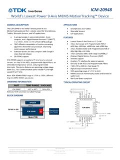
1 ICM- 20789 7- axis , High Performance Integrated 6- axis Inertial and Barometric Pressure sensor InvenSense reserves the right to change the detail specifications as may be required to permit improvements in the design of its products. TDK Corporation 1745 Technology Drive, San Jose, CA 95110 +1(408) 988 7339 Document Number: DS-000169 Revision: Revision Date: 10/31/2017 GENERAL DESCRIPTION The 7- axis ICM- 20789 is an integrated 6- axis inertial device that combines a 3- axis gyroscope, 3- axis accelerometer, and an ultra-low noise MEMS capacitive pressure sensor in a 24-pin LGA package. This unique 7- axis device offers performance of discrete components in a single small footprint for tracking rotational and linear motion as well as pressure differences with an accuracy of 1 Pa, an accuracy enabling altitude measurement differentials as small as cm. The pressure sensor s MEMS capacitive architecture provides the industry s lowest noise at the lowest power, high sensor throughput, and temperature coefficient offset of Pa/ C.
2 The pressure sensor s combination of high accuracy elevation measurements, low power, and temperature stability complemented by the motion tracking 6- axis inertial sensor in a small footprint, make it ideal for a wide range of motion tracking applications. The embedded 6- axis MotionTracking device combines a 3- axis gyroscope, 3- axis accelerometer, and a Digital motion Processor (DMP). An available large 4 kB FIFO reduces traffic on the serial bus interface, and power consumption through burst sensor data transmission. The Gyroscope has programmable FSR of 250 dps, 500 dps, 1000 dps and 2000 dps. The Accelerometer FSR is programmable to 2g, 4g, 8g and 16g ICM- 20789 has 16-bit ADC for the 6- axis inertial sensor and 24-bit ADC for the pressure sensor , programmable digital filters, two temperature sensors one each in 6- axis Inertial and Pressure sensor . The device features an operating voltage of Communication port includes I2C at 400 kHz (6- axis and Pressure) and 8 MHz SPI (6- axis only).
3 The package is mm 24-pin to minimize board area requirements. BLOCK DIAGRAM APPLICATIONS Drones and Flying Toys motion -based gaming controllers Virtual Reality headsets and controllers Indoor/Outdoor Navigation (dead-reckoning, floor/elevator/step detection) FEATURES Pressure operating range: 30 to 110 kPa Noise and current consumption o Pa @ A (LP mode) o Pa @ A (LN mode) o Pa @ A (ULN mode) Pressure sensor Relative Accuracy: 1 Pa for any 10 hPa change over 950 hPa-1050 hPa at 25 C Pressure sensor Absolute Accuracy: 1 hPa over 950 hPa-1050 hPa, 0 C to 65 C Pressure sensor Temperature Coefficient Offset: Pa/ C over 25 C to 45 C at 100 kPa Gyroscope programmable FSR of 250 dps, 500 dps, 1000 dps, and 2000 dps Accelerometer with Programmable FSR of 2g, 4g, 8g, and 16g Large 4 kB FIFO reduces traffic on the serial bus interface EIS FSYNC support User-programmable interrupts Wake-on- motion interrupt for low power operation of applications processor Host interface: 400 kHz Fast Mode I2C & 8 MHz SPI (see datasheet for ICM-20689) Digital-output temperature sensor (x2) Nominal VDD operation at RoHS and Green compliant ORDERING INFORMATION PART TEMP RANGE PACKAGE ICM- 20789 40 C to +85 C 24-Pin LGA Denotes RoHS and Green-Compliant Package I2C AP/HUB ICM- 20789 SPI (6- axis only) 6- axis motion Pressure sensor I2C I2C ICM- 20789 Document Number: DS-000169 Page 2 of 62 Revision: TABLE OF CONTENTS General Description.
4 1 Block Diagram .. 1 Applications .. 1 Features .. 1 Ordering Information .. 1 1 Introduction .. 7 Purpose and Scope .. 7 Product 7 Applications .. 7 2 Features .. 8 Gyroscope Features .. 8 Accelerometer Features .. 8 Pressure sensor Features .. 8 Additional Features .. 8 motion Processing .. 8 3 Electrical Characteristics .. 9 Gyroscope Specifications .. 9 Accelerometer Specifications .. 10 Pressure sensor Specifications .. 11 Electrical Specifications .. 12 I2C Timing Characterization .. 14 Absolute Maximum Ratings .. 16 4 Applications Information .. 17 Pin Out Diagram and Signal Description .. 17 Typical Operating Circuit .. 18 Bill of Materials for External Components .. 21 Block Diagram .. 22 Overview .. 23 Three- axis MEMS Gyroscope with 16-bit ADCs and Signal Conditioning .. 24 Three- axis MEMS Accelerometer with 16-bit ADCs and Signal Conditioning .. 24 Digital motion Processor.
5 24 Pressure sensor .. 24 I2C Serial Communications Interface .. 24 Self-Test .. 25 Clocking .. 26 sensor Data Registers .. 26 FIFO .. 26 Interrupts .. 26 Digital-Output Temperature sensor .. 26 ICM- 20789 Document Number: DS-000169 Page 3 of 62 Revision: Bias and LDOs .. 26 Charge Pump .. 26 Standard Power Modes Update the power modes .. 27 5 Programmable Interrupts .. 28 Per axis Wake-on- motion Interrupt .. 28 6 Digital Interface .. 29 I2C Serial Interface .. 29 I2C Interface .. 29 I2C Communications Protocol (6- axis only. For pressure please see chapter 10) .. 29 I2C Terms .. 31 7 Serial Interface Considerations .. 33 ICM- 20789 Supported Interfaces .. 33 8 Register Map .. 34 9 Register Descriptions .. 36 Registers Descriptions .. 36 Registers 0 to 2 Self-Test Registers .. 36 Registers 13 to 15 .. 36 Register 19 Gyro Offset Adjustment Register .. 36 Register 20 Gyro Offset Adjustment Register.
6 36 Register 21 Gyro Offset Adjustment Register .. 37 Register 22 Gyro Offset Adjustment Register .. 37 Register 23 Gyro Offset Adjustment Register .. 37 Register 24 Gyro Offset Adjustment Register .. 37 Register 25 Sample Rate Divider.. 37 Register 26 Configuration .. 38 Register 27 Gyroscope Configuration .. 38 Register 28 Accelerometer Configuration .. 39 Register 29 Accelerometer Configuration 39 Register 30 Low Power Mode Configuration .. 40 Register 32 Wake on motion Threshold .. 41 Register 33 Wake on motion Threshold .. 41 Register 34 Wake on motion Threshold .. 41 Register 35 FIFO Enable .. 42 Register 55 Interrupt/Bypass Pin Configuration .. 42 Register 56 Interrupt Enable .. 43 Register 57 DMP Interrupt Status .. 43 Register 58 Interrupt Status .. 43 Register 59 Accelerometer Measurements .. 43 Register 60 Accelerometer Measurements.
7 43 Register 61 Accelerometer Measurements .. 44 ICM- 20789 Document Number: DS-000169 Page 4 of 62 Revision: Register 62 Accelerometer Measurements .. 44 Register 63 Accelerometer Measurements .. 44 Register 64 Accelerometer Measurements .. 44 Register 65 Temperature Measurement .. 44 Register 66 Temperature Measurement .. 44 Register 67 Gyroscope Measurement .. 44 Register 68 Gyroscope Measurement .. 45 Register 69 Gyroscope Measurement .. 45 Register 70 Gyroscope Measurement .. 45 Register 71 Gyroscope Measurement .. 45 Register 72 Gyroscope Measurement .. 45 Register 104 Signal Path Reset .. 45 Register 105 Accelerometer Intelligence Control .. 46 Register 106 User Control .. 46 Register 107 Power Management 1 .. 47 Register 108 Power Management 2 .. 47 Register 114 FIFO Count Registers .. 47 Register 115 FIFO Count Registers .. 48 Register 116 FIFO Read Write.
8 48 Register 117 Who Am I .. 48 Register 119 Accelerometer Offset 48 Register 120 Accelerometer Offset 49 Register 122 Accelerometer Offset 49 Register 123 Accelerometer Offset 49 Register 125 Accelerometer Offset 49 Register 126 Accelerometer Offset 49 10 Pressure sensor How to Read .. 50 I2C Operation And Communication .. 50 11 Assembly .. 55 Orientation of Axes .. 55 Implementation and usage recommendations .. 55 Package Dimensions .. 56 12 Part Number Package Marking .. 58 13 Ordering Guide .. 59 14 Reference .. 60 15 Revision History .. 61 ICM- 20789 Document Number: DS-000169 Page 5 of 62 Revision: LIST OF FIGURES Figure 1. I2C Bus Timing Diagram .. 15 Figure 2. Pin out Diagram for ICM- 20789 .. 17 Figure 3. I2C Communication Supply Schematic .. 18 Figure 4. I2C Communication MCU Interface at 3V or Schematic .. 19 Figure 5. SPI Communication for Gyro/Accel; I2C for Pressure Schematic.
9 20 Figure 6. SPI Communication for Gyro/Accel; I2C Pressure; MCU Digital Interface: Schematic .. 20 Figure 7. SPI Communication for Gyro/Accel; I2C for Pressure; MCU Digital Interface: 21 Figure 8. ICM- 20789 Block Diagram (I2C interface).. 22 Figure 9. ICM- 20789 Block Diagram (SPI/ I2C interface) .. 23 Figure 10. ICM- 20789 Solution Using I2C Interface .. 25 Figure 11. START and STOP Conditions .. 29 Figure 12. Acknowledge on the I2C Bus .. 30 Figure 13. Complete I2C Data Transfer .. 30 Figure 14. I/O Levels and Connections .. 33 Figure 15. Communication Sequence for starting a measurement and reading measurement results .. 54 Figure 16. Orientation of Axes of Sensitivity and Polarity of Rotation .. 55 Figure 17. Package 56 Figure 18. ICM- 20789 recommended PCB land pattern .. 57 Figure 19. Part Number Package Marking .. 58 ICM- 20789 Document Number: DS-000169 Page 6 of 62 Revision: LIST OF TABLES Table 1.
10 Gyroscope Specifications .. 9 Table 2. Accelerometer Specifications .. 10 Table 3. Operation Ranges .. 11 Table 4. Operation Modes .. 11 Table 5. Pressure sensor Specifications .. 11 Table 6. Temperature sensor Specifications .. 12 Table 7. Electrical Characteristics .. 12 Table 8. Electrical Characteristics (6- axis ) .. 13 Table 9. Electrical Characteristics (Pressure sensor ) .. 14 Table 10. Other Electrical Specifications .. 14 Table 11. I2C Timing Characteristics .. 15 Table 12. Absolute Maximum Ratings (6- axis ) .. 16 Table 13. Absolute Maximum Ratings (pressure sensor ).. 16 Table 14. Signal Descriptions .. 17 Table 15. Bill of Materials .. 21 Table 16. Standard Power Modes for 27 Table 17. Table of Interrupt Sources .. 28 Table 18. Serial Interface .. 29 Table 19. I2C Term SPI Interface .. 31 Table 20. Register Map .. 35 Table 21. Accelerometer Data Rates and Bandwidths (Low Noise Mode) .. 39 Table 22. Accelerometer Data Rates and Bandwidths (Low-Power Mode).