Transcription of Inspiron 7000 User's Guide - Dell
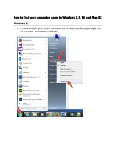
1 dell Inspiron 7000 Specifications Jumpers, Switches, Controls, and Indicators Tech Notes Documentation Graphics Initial release: 26 Aug 1998 Last revised: 17 Aug 1999 LCD Brackets and Carrier Tray Removal: dell Inspiron 7000 This procedure assumes that you have removed the front bezel and the LCD panel. To remove the brackets from the LCD panel, follow these steps: the LCD wire harness from connector CN1 on the top left side of the inverter board. the (4) 6-mm screws from the sides of the mounting brackets. the brackets from the LCD panel. To remove the LCD panel from the carrier tray, follow these steps: any Kapton tape covering the CCFL cable. pull the cable out of its connector. any Kapton tape from the LCD wire harness. the LCD wire harness from the LCD panel. the LCD panel out of carrier tray. NOTICE: The metal on the carrier tray is sharp. Be careful not to cut LCD Panel Removal: dell Inspiron 7000 This procedure assumes that you have removed the front bezel.
2 Follow these steps to remove the LCD panel: the (8) 6-mm screws that secure the left and right LCD brackets to the front plastic cover. the LCD wire harness from connector CN2 on the right side of inverter board. present, carefully remove the grounding tape between the inverter board and LCD panel. the 3-mm screw securing the inverter board. the LCD panel, LCD brackets, and carrier tray, as a unit, out of the back cover. Rotate upward from the bottom of the panel because the top slides underneath the plastic hooks. the hinges, which were previously held in place by pressure and screws. To remove the inverter board, follow these steps: the 3-mm screw securing the inverter board to the back cover. you have not removed the LCD panel, disconnect the LCD wire harness from connectors CN1 and CN2 on the inverter board. the inverter board from the back cover. LCD Panel, Brackets, and Carrier Tray Removal: dell Inspiron 7000 This procedure assumes that you have removed the front bezel.
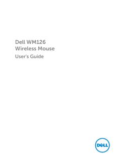
3 Follow these steps to remove the LCD panel: the (8) 6-mm screws that secure the left and right LCD brackets to the front plastic cover. the CCFL cable from connector CN2 on the right side of inverter board. remove the grounding tape between the inverter board and LCD panel. the 3-mm screw securing the inverter board, and unsnap the inverter board from the back cover. the LCD panel, LCD brackets, and inverter board as one unit out of the back cover. Rotate upward from the bottom of the panel because the top slides underneath the plastic hooks. the hinges, which were previously held in place by pressure and screws. To remove the LCD brackets from the LCD panel, follow these steps: the (4) 4-mm screws from the sides of the LCD brackets. the brackets from the LCD panel. To remove the LCD panel from the carrier tray, follow these steps: the inverter board shield, pull it slightly away from the panel to expose the cabling, and detach the LCD wire harness from connector CN1 on the inverter board.
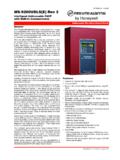
4 Any Kapton tape covering the CCFL cable on the back of the LCD. pull the interposer board off the connector to the LCD panel. the LCD panel up and remove any tape between the LCD wire harness and the carrier tray. the LCD wire harness from the LCD panel. the LCD panel out of the carrier tray. the LCD wire harness from the LCD panel. NOTICE: The metal on the carrier tray is sharp. Be careful not to cut LCD Panel Removal: dell Inspiron 7000 To remove the 15-inch LCD panel, perform the following steps: the computer over and remove the 4 screws from the bottom of the computer. the computer back over and open the display. the plastic hinge covers. a small flat-blade screwdriver or a similar plastic tool along the top-right edge of the keyboard, above the row of function keys. Working from right to left, free the keyboard by prying it toward the front of the unit. When free, lift the top of the keyboard slightly to clear the palmrest assembly.
5 The keyboard bracket (located in the upper-right corner of the keyboard). the four screws that secure the two hinges. the LCD wire harness and lift the assembly off the computer base. To remove the front bezel, follow these steps: the two rubber screw covers and screws on the LCD near the hinge. Remove the remaining three plastic screw covers and screws, one on either side and one in the front. all screws removed, unsnap the front bezel from the back cover and remove the bezel from the assembly. To remove the LCD panel, hinges, and inverter board, follow these steps: the 4 remaining screw covers and screws on the sides of the LCD. all screws removed, lift the LCD panel out and disconnect the CCFL wire from the inverter board. the LCD wire harness from connector CN2 on the right side of the inverter board. remove the grounding tape between the inverter board and the LCD panel. the two screws securing the inverter board to the back cover.
6 The inverter board from the back cover. To reassemble, perform the steps in reverse order. AC Adapter: dell Inspiron 7000 Audio Jacks: dell Inspiron 7000 Audio Devices: dell Inspiron 7000 You can connect speakers, a microphone, headphones, and record/playback devices such as cassette players, CD players, and VCRs to the sound jacks on the computer. dell recommends using amplified speakers for the best sound. Connect headphones or speakers to the line-out jack on the far right of the sound jacks. Connect a microphone to the microphone jack in the middle. Connect record/playback devices such as cassette players, CD players, and VCRs to the line-in jack on the far left. See your Microsoft windows 98 documentation for the location of sound applications such as mixers and volume control . You can control the sound coming from the external speakers and from the computer's built-in speakers with the volume control dial. You can also use the keyboard to adjust the volumes.
7 Press <Fn> <Page Down> to lower the volume. Press <Fn> <Page Up> to increase the volume. Press <Fn> <End> to enable or disable both the built-in and external speakers. See Reinstalling Utilities and Drivers for information about reinstalling the audio drivers. The drivers are located on the dell Inspiron 7000 System Software CD. NOTE: If no sound comes from the speakers, make sure that the sound is not disabled by pressing <Fn> <End> and checking the volume control Card and Audio Thermal Shield Removal: dell Inspiron 7000 This procedure assumes that you have removed the system board from the plastic case and have removed the PC Card cage from the system board. To remove the audio card and audio thermal shield, follow these steps: pull the audio card off of connectors JP12 and JP13 on the system board. Do not rock the card to remove it, because this may damage the connectors. the 10-mm screw securing the audio thermal shield, and then remove the shield.
8 Component Locations (Back View): dell Inspiron 7000 Base Assembly Component Removal: dell Inspiron 7000 Base Assembly | Base Assembly Component Removal Base Assembly Base Assembly Component Removal The following procedures assume that the keyboard, thermal shield, display assembly, and palmrest assembly have been removed. PC Card Heat Sink Removal Heat Exchanger/Fan Removal DC-DC Board Removal LVDS Board Removal Processor Board and Memory Module Removal Hinge Saddle Removal RJ-11 Card Removal System Board Removal PC Card Cage Removal Audio Card and Audio Thermal Shield Removal Latch Assembly Removal Battery Charge Gauge: dell Inspiron 7000 Removing and Installing a Battery: dell Inspiron 7000 Front Bezel Removal: dell Inspiron 7000 This procedure assumes that you have removed the display assembly from the computer base. To remove the front bezel, follow these steps: a dental pick to pry the rubber screw covers off of the bottom 2 screws and the rubber bumpers off of the top 2 screws.
9 The (4) 6-mm screws from the front bezel. the front bezel from the back cover and remove it from the assembly. Carefully insert your fingers between the LCD panel and the bezel. Roll the plastic up slightly to insert your fingers further in, and then lift upward to free the snaps. Start at the middle bottom and then work around. When replacing the bezel, ensure that the LCD wire harness is routed correctly through the openings in the back cover and is not pinched. DC-DC Board Removal: dell Inspiron 7000 To remove the DC-DC board, gently pull the DC-DC board off of connectors JP11 and JP16 on the system board. Do not rock the board to remove it, because this may damage the connectors. Display Assembly and Display Assembly Component Removal: dell Inspiron 7000 Display Assembly Removal | Display Assembly Component Removal Display Assembly Removal This procedure assumes that you have removed the keyboard and thermal shield. To remove the display assembly from the computer, follow these steps: the LCD wire harness from connector JP3.
10 Use a dental pick or flat-blade screwdriver to pry up each end of the connector to release it. the display. the (4) 6-mm screws that secure the 2 hinges. the display assembly and lift the assembly off the computer base. Display Assembly Component Removal Front Bezel Removal LCD Panel Removal LCD Brackets and Carrier Tray Removal LCD Panel, Brackets and Carrier Tray Removal 15-Inch LCD Panel Removal Back to Contents Page Documentation: dell Inspiron 7000 Printed Documentation | Online Documentation Printed Documentation To save PDF files (files with an extension of .pdf) to your hard-disk drive, right-click the document title, click Save Target As in Microsoft Internet Explorer or Save Link As in Netscape Navigator, and specify a location on your hard-disk drive. Right-click only the following links: dell Inspiron 7000 Reference and Troubleshooting Guide (.pdf) dell Inspiron 7000 Series Installing Drivers and Utilities ( windows 98) (.)