Transcription of INST99-7315 - Metra Online
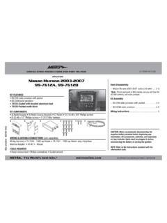
1 INSTALLATION INSTRUCTIONS FOR PART 99-3051 Phillips Screwdriver Rotary Cutting Tool1-800-221-0932 FEATURES COPYRIGHT 2004-2009 Metra ELECTRONICS CORPORATION ISO mount Radio Provision with Pocket Two ISO Mount Unit s Provision Double DIN Radio Provision ( A) Pocket ( B) Brackets ( C) Trim Plate ( D) (4) #6 X 1/4 Phillips Head Screws (E) (2) #8 X 3/8 Phillips Head Screws KIT COMPONENTSTOOLS REQUIRED:99-3051 ACDEAPPLICATIONSC hevrolet Corvette1990-1996 BWIRING AND ANTENNA CONNECTIONS (Sold Separately)Wiring Harness: 70-1856 - 17ft bypass harness (Non-Bose) 1989-1996 70-1857 - 17ft bypass harness (Bose) 1989-1996 Antenna Adapter: Not requiredDash Disassembly 1990-1996 chevrolet Corvette.
2 1, 2 Kit Assembly ISOM ount Radio Provision with Pocket .. 3 Double DINR adio Provision .. 4 TwoISO Mount Unit s Provision .. 4 Final Assembly .. 5 TABLE OF CONTENTS99-3051 KNOWLEDGE IS POWERE nhance your installation and fabrication skillsbyenrolling in the most recognized andrespectedmobile electronics school in our onto for more information and take steps toward a better the negative battery terminal to prevent an accidentalshort (2) screws from center ACvent and remove vent. (Figure A)21990-1996 chevrolet CORVETTER emove rubber inserts in cup hold-ers and remove screw.
3 (Figure B)3 Remove (2) screws from under carpetinside center parking brake and place shifterinto the drive the center console up and slideback. (Figure C)6 DASH DISASSEMBLYABCR emove (3) screws from radio/clim-ate control trim panel and removepanel. (Figure C)7 Remove (2) screws from side trimpanels to gain access to radioscrews and remove (4) screwssecuring radio, unplug and DISASSEMBLYCUT OUTD1990-1996 chevrolet CORVETTECut and remove obstruction fromrear of radio cavity. (Figure D)999-3051 KIT ASSEMBLYM ount the pocket trim-plate to thepocket using the (2) #8x3/8 Phillipshead screws provided with lip towards top of pocket.
4 (Figure A)1 Continue to final the mounting holes in thebrackets with the mounting holes inthe side of the radio and mount thebrackets to the radio using screwsprovided with the radio. (Figure B)2 Align the mounting holes in the brack-ets below the radio with the mountingholes in the pocket and mount thepocket to the brackets using the (4)#6x1/4 Phillips head screws providedwith the kit. (Figure C)3 ISO MOUNT RADIO WITH POCKETABC31990-1996 chevrolet CORVETTE499-3051 KIT ASSEMBLYA lign the mounting holes in the leftbracket with the mounting holes inthe left side of the radio and mountthe bracket to the radio usingscrews provided with the radio.
5 (Figure A)1 Align the mounting holes in the leftbracket with the mounting holes in theleft side of both units and mount thebracket to both units using screwsprovided with the units. (Figure A)1 Continue to final step one with the rightbracket on the right side of the to final step one with the right bracketon the right side of the DIN RADIO PROVISIONTWO ISO MOUNT UNITSAA1990-1996 chevrolet CORVETTE5 FINAL ASSEMBLY1 Locate the factory wiring harness in the dash and make the connection as shown. Metra recomends using the proper mating adapter and making the connections asshown.
6 (Isolate and individually tape off the ends of any unused wires to preventelectrical short circuit.)2Re-connect the negative battery terminal and test the unit for proper radio and dash assemblies in reverse order of )Strip wire ends back 1/2"B)Twist ends togetherC)SolderD)TapeBCDMake wiring connections using the EIA color code chart shown below and the instructions included with the headunit. Metra recommends making connections as shown below; Strip, Splice, Solder, Tape. Isolate and individuallytape off ends of any unused wires to prevent electrical short Ignition / Acc.
7 Red12V Batt / Memory .. YellowGround .. Black*Power Antenna .. BlueAmp Turn-On .. Blue / WhiteAmp Ground .. Black / WhiteIllumination.. OrangeDimmer .. Orange / WhiteRight Front (+) .. GrayRight Front (-) .. Gray / BlackLeft Front (+) .. WhiteLeft Front (-) .. White / BlackRight Rear (+).. VioletRight Rear (-) .. Violet / BlackLeft Rear (+) .. GreenLeft Rear (-).. Green / Black*NOTE: When a Black wire is not present,ground radio to vehicle colors may not be present on all leads due to manufacturer s / EIA WIRING CODEFINAL WIRING CONNECTIONS99-3051 FINAL ASSEMBLYINST9930511-800-221-0932 06/05/09 COPYRIGHT 2004-2009 Metra ELECTRONICS CORPORATION inst99 -3051