Transcription of INSTALLATION AND OPERATING INSTRUCTIONS …
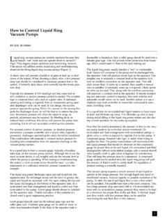
1 671 0294 MODELSHPMEDIUM HEAD MODELSHIGH HEAD MODELS1/3 JBMB-56S JMB-56L JBHB-61S JHB-61HL 1/2 JBMC-56 SJBMC3-56 SJMC-56 LJMC3-56 JBHC-61 SJBHC3-61 SJHC-61 HLJHC3-61H3/4 JBMD-57 SJBMD3-57 SJMD-57 LJMD3-57 JBHD-62 SJBHD3-62 SJHD-62 HLJHD3-62H1 JBME-58 SJBME3-58 SJME-58 LJME3-58 JBHE-63 SJBHE3-63 SJHE-63 HLJHE3-63H1-1/2 JBMF-40 SJBMF3-40 SJMF-40 LJMF3-40 JBHF-51 SJBHF3-51 SJHF-51 HLJHF3-51H2 JBMG-41 SJBMG3-41 SJMG-41 LJMG3-41 JBHG-52 SJBHG3-52 SJHG-52 HLJHG3-52H2-1/2 JBMMG-59 SJBMMG3-59S JBHHG-53 SJBHHG3-53 SJHHG-53 HLJHHG3-53 HOWNER S MANUAL60 Cycle J and JB SeriesCentrifugal PumpINSTALLATION AND OPERATING INSTRUCTIONSREPAIR PARTS LIST 2014 Pentair Ltd. All Rights Reserved. S873 (Rev. 12/16/14)293 WRIGHT STREET, DELAVAN, WI 53115 : 888-782-7483 Support suction pipeas requiredSupport discharge pipe as requiredAs closeas possible4 x "D"minimumFoot ValvePipe diameter"D"Straight run, short aspossible but at least 6times pipe diameter ("D")sloping away from pumpShort length of straight pipeafter reducerImportant:All connections mustbe air tightEccentricReducerSolid, levelbaseTee andPriming PlugRotated VoluteGateValveUnionDischarge to serviceRecommended pump suctionand discharge connectionsVentPlugPrimingPlugStreet ElbowNot recommended pump suctionand discharge connections Elbow immediately in front of pump the discharge avoid.
2 Quick closing turns in piping diameter "D"insufficient sizePipe submergedless than 4 x "D"will cause vortexingLong suctionrunConcentricReducerUse of excess fittingsmeans potential air leaksValveUnsupportedPipeConcentric Reducer causes highspots along the suction line resultingin air 0294 Figure 1 Figure 223 California Proposition 65 Warning This product and related accessories contain chemicals known to the State of California to cause cancer, birth defects or other reproductive - GENERALS upport both suction and discharge piping independently at a point near the pump to avoid putting a strain on the pump housing. Start all piping AT THE pipe diameter at both the suction and discharge by one (1) standard pipe size ( minimum ) to obtain desired performance and flow rate. Refer to Table I when sizing pipe for your pumping : Do not use pipe with smaller diameter on the suction side of I Pipe Tapping Recommended Size On Pump Pipe Size Suction Discharge Suction Discharge 1-1/4 1 1-1/2 1-1/4 1-1/2 1-1/4 2 1-1/2 2 1-1/2 3 2 SUCTION PIPEI ncrease pipe size from pump tapping as shown in Table 1 (Page 2) depicts a recommended run of pipe and fittings for the suction side of a centrifugal pump.
3 Please refer to this illustration when choosing pipe and fittings for your suction : All connections must be air tight!Figure 2 (Page 2) depicts conditions that are NOT DESIRABLE on the suction side of a centrifugal pump and may cause problems in flow rate and priming. Please look this illustration over carefully before choosing pipe and fittings for your suction PIPINGI ncrease pipe size from pump tapping as show in Table I. Figure 1 (Page 2) depicts a recommended run of pipe and fittings for the discharge. Install tee with priming plug as close to pump as possible. Figure 2 (Page 2) notes conditions that should be avoided. Please read over carefully before making discharge THE PUMPA pump is primed when all air in the suction line and pump volute has been evacuated and replaced with Prime:1. Close valve in discharge Remove priming plug from tee and fill pump and suction line with water until water is flowing back out of Replace priming Start pump and slowly open valve until desired water flow is achieved.
4 NOTICE: If water is not being pumped, turn off pump, close valve, and repeat steps 1 thru pump volute is rotated as shown in Figure 1 (Page 2), loosen vent plug when priming to evacuate air trapped inside volute and tighten when volute is completely filled with water. Risk of explosion and scalding. Never run pump against closed discharge. To do so can boil water inside pump, causing hazardous pressure buildup and possible explosion. Risk of flooding. Do not run the pump dry. This will damage mechanical seal and void warranty. It may cause burns to person handling pump. Motor normally operates at high temperature and will be too hot to touch. It is protected from heat damage during operation by an automatic internal cutoff switch. Before handling pump or motor, stop motor and allow it to cool for 20 II - RECOMMENDED FUSING AND WIRING DATA - 60 CYCLE MOTORSMOTORHPMAX. LOADAMPERESBRANCHFUSE*RATINGAMPSDIAMETER IN FEET FROM MOTOR TO METER0 TO 50 51 TO 100 101 TO 200 201 TO 300 301 TO 400 401 TO 500 WIRE SIZESINGLE PHASE - 115/230 VOLT1 PHASE - 230/460 VOLT1 * Time delay fuse or circuit breakers are recommended in any motor diagram for dual voltage, single-phase motors.
5 Your dual-voltage motor s terminal board (under the motor end cover) will match one of the diagrams below. Follow that diagram if necessary to convert motor to 115 Volt power. Connect power supply wires to L1 and L2. For 3-phase motors, or if motor does not match these pictures, follow the connection diagram on the motor MOTOR IS SET FOR 230 VOLTS WHEN change the motor to use 115 volts:1. Turn off power2. Remove the back motor Use a screwdriver or 1/2 wrench and turn the voltage selector dial counterclockwise until 115 shows in the dial Reinstall the motor cover. Hazardous voltage. Can shock, burn, or cause death. Disconnect power to motor before working on pump or motor. Ground motor before connecting to power Ground motor before connecting to electrical power supply. Failure to ground motor can cause severe or fatal electrical shock hazard. Do not ground to a gas supply line. To avoid dangerous or fatal electrical shock, turn OFF power to motor before working on electrical connections.
6 Supply voltage must be within 10% of nameplate voltage. Incorrect voltage can cause fire or damage motor and voids warranty. If in doubt consult a licensed electrician. Use wire size specified in Wiring Chart (Page 3). If possible, connect pump to a separate branch circuit with no other appliances on it. Wire motor according to diagram on motor nameplate. If nameplate diagram differs from diagrams above, follow nameplate Install, ground, wire and maintain your pump in compliance with the National Electrical Code (NEC) in the , or the Canadian Electrical Code (CEC), as applicable, and with all local codes and ordinances that apply. Consult your local building inspector for code Provide a correctly fused disconnect switch for protection while working on motor. For switch requirements, consult your local building inspector for information about Disconnect power before servicing motor or pump.
7 If the disconnect switch is out of sight of pump, lock it open and tag it to prevent unexpected power Ground the pump permanently using a wire of the same size as that specified in wiring chart (Page 3). Make ground connection to green grounding terminal under motor canopy marked GRD. or . 5. Connect ground wire to a grounded lead in the service panel or to a metal underground water pipe or well casing at least 10 feet long. Do not connect to plastic pipe or insulated Protect current carrying and grounding conductors from cuts, grease, heat, oil, and Connect current carrying conductors to terminals L1 and L2 under motor canopy. When replacing motor, check wiring diagram on motor nameplate against Figure ##. If the motor wiring diagram does not match either diagram in Figure 3, follow the diagram on the : 115/230 Volt single phase models are shipped from factory with motor wired for 230 volts.
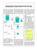
8 If power supply is 115 volts, remove motor canopy and reconnect motor as shown in Figure 3. Do not try to run motor as received on 115 volt Motor has automatic internal thermal overload protection. If motor has stopped for unknown reasons, thermal overload may restart it unexpectedly, which could cause injury or property damage. Disconnect power before servicing If this procedure or the wiring diagrams are confusing, consult a licensed 3: Changing the Voltage SettingFigure 4: Motor Set for 115 Volt Operation5 Seal PlateMechanical sealrotating halfMechanical sealstationary halfA-Seal removal-rotating halfB-Seal removal-stationary halfC-Stationary half installationD-Rotating half installationTurn over PolishedsurfaceRubbersurfaceCardboardwas her(supplied w/seal)3/4" socket or pipeSealingfaceRubber driveringImpellerShaftshoulder5939 0109 FIGURE 5 PUMP SERVICEThis centrifugal pump requires little or no service other than reasonable care and periodic cleaning.
9 Occasionally, howev-er, a shaft seal may become damaged and must be replaced. The procedure as outlined below will enable you to replace the : Pumps use mechanical seals with a rubber seat ring or a sealing O-Ring. THESE SEALS ARE COMPLETELY : The highly polished and lapped faces of this seal are easily damaged. Read INSTRUCTIONS and handle the seal with models are equipped with an impeller screw, which has a left hand thread. Before unscrewing the impeller, remove the impeller OF OLD SEAL1. After unscrewing impeller, carefully remove rotating part of seal by prying up on sealing washer, using two screw-drivers (see Figure 5A). Use care not to scratch motor Remove seal plate from motor and place on flat surface, face down. Use a screwdriver to push ceramic seat out from seal cavity (see Figure 5B). INSTALLATION OF FLOATING SEAT (Figure 5C)1.
10 Clean polished surface of floating seat with clean Turn seal plate over so seal cavity is up, clean cavity Lubricate outside rubber surface of ceramic seat with soapy water and press firmly into seal cavity with finger pressure. If seat will not locate properly in this manner, place cardboard washer over polished face of seat and press into seal cavity using a 3/4 socket or 3/4 piece of standard DISPOSE OF CARDBOARD WASHER. Be sure polished surface of seat is free of dirt and has not been damaged by insertion. Remove excess soapy OF ROTATINGPART OF SEAL UNIT (Figure 5D)1. Reinstall seal plate using extreme caution not to hit ceram-ic portion of seal on motor Inspect shaft to make sure that it is Clean face of sealing washer with clean Lubricate inside diameter and outer face of rubber drive ring with soapy water and slide assembly on motor shaft (sealing face first) until rubber drive ring hits shaft Screw impeller on shaft until impeller hub hits shaft shoul-der.