Transcription of NOTICE D’UTILISATION Pompes à éjecteur pour …
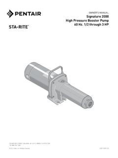
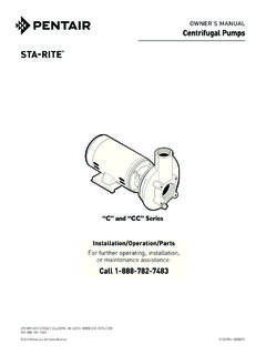
1 OWNER S MANUALS hallow Well Jet PumpsNOTICE D UTILISATIONP ompes jecteur pour puits peu profondsMANUAL DEL PROPIETARIOB ombas tipo Jet para pozos poco profundosInstallation/Operation/PartsFor further operating, installation,or maintenance assistance: Call 888-782-7483 English .. Pages 2-14 Installation/Fonctionnement/Pi cesPour plus de renseignements concernant l utilisation, l installation ou l entretien,composer le 888-782-7483 Fran ais .. Pages 15-27 Instalaci n/Operaci n/PiezasPara mayor informaci n sobre el funcionamiento, instalaci n o mantenimiento de la bomba:llame al 888-782-7483 Espa ol .. Paginas 28-402400 0496 NFSN Series / S rie SN / Serie SNHN Series / S rie HN / Serie HN 2012 Pentair, Inc. All Rights Reserved. S376 (11/05/12)293 WRIGHT STREET, DELAVAN, WI 53115 : 888-782-7483 Safety 2 READ AND FOLLOW SAFETY INSTRUCTIONS!
2 This is the safety alert symbol. When you see this symbol on your pump or in this manual, look for one of the following signal words and be alert to the potential for personal injury:warns about hazards that will cause serious personal injury, death or major property damage if about hazards that can cause serious personal injury, death or major property damage if about hazards that will or can cause minor personal injury or property damage if label NOTICE indicates special instructions which are important but not related to read and follow all safety instructions in this manual and on safety labels in good condition. Replace missing or damaged safety labels. California Proposition 65 WarningThis product and related accessories contain chemicals known to the State of California to cause cancer, birth defects or other reproductive SAFETYC apacitor voltage may be hazardous.
3 To discharge motor capacitor, hold insulated handle screwdriver BY THE HANDLE and short capacitor terminals together. Do not touch metal screwdriver blade or capacitor terminals. If in doubt, consult a qualified electrician. GENERAL SAFETYDo not touch an operating motor. Modern motors are designed to operate at high temperatures. To avoid burns when servicing pump, allow it to cool for 20 minutes after shut-down before not allow pump or any system component to freeze. To do so will void water only with this inspect pump and system safety glasses at all times when working on work area clean, uncluttered and properly lighted; store properly all unused tools and visitors at a safe distance from the work body may explode if used as a booster pump unless relief valve capable of passing full pump flow at 75 psi is pressure!
4 Install pressure relief valve in discharge all pressure on system before working on any voltage. Can shock, burn, or cause pump before connecting to power supply. Disconnect power before working on pump, motor or motor for correct voltage. See Electri cal sec-tion of this manual and motor motor before connecting to power National Electri cal Code, Canadian Elec tri cal Code, and local codes for all wiring instruc-tions in this manual when con-necting motor to power of Contents 3 PageGeneral Safety .. (Well Pumps) ..4, 5 Connecting Discharge Booster System ..7 Electrical ..8, 9 Preparing To Start The Pump ..10 Repair Parts ..11-13 Troubleshooting ..14 Limited WarrantySTA-RITE warrants to the original consumer purchaser ( Purchaser or You ) of the products listed below, that they will be free from defects in material and workmanship for the Warranty Period shown below.
5 ProductWarranty PeriodWater Systems Products jet pumps, small centrifugal pumps, submersible pumps and related accessorieswhichever occurs first: 12 months from date of original installation, or 18 months from date of manufacturePro-Source Composite Tanks5 years from date of original installationPro-Source Steel Pressure Tanks5 years from date of original installationPro-Source Epoxy-Lined Tanks3 years from date of original installationSump/Sewage/Effluent Products12 months from date of original installation, or 18 months from date of manufactureOur warranty will not apply to any product that, in our sole judgement, has been subject to negligence, misapplication, improper installation, or improper maintenance. Without limiting the foregoing, operating a three phase motor with single phase power through a phase converter will void the warranty.
6 Note also that three phase motors must be protected by three-leg, ambient compensated, extra-quick trip overload relays of the recommended size or the warranty is only remedy, and STA-RITE s only duty, is that STA-RITE repair or replace defective products (at STA-RITE s choice). You must pay all labor and shipping charges associated with this warranty and must request warranty service through the installing dealer as soon as a problem is discovered. No request for service will be accepted if received after the Warranty Period has expired. This warranty is not SHALL NOT BE LIABLE FOR ANY CONSEQUENTIAL, INCIDENTAL, OR CONTINGENT DAMAGES FOREGOING WARRANTIES ARE EXCLUSIVE AND IN LIEU OF ALL OTHER EXPRESS AND IMPLIED WARRANTIES, INCLUDING BUT NOT LIMITED TO THE IMPLIED WARRANTIES OF MERCHANTABILITY AND FITNESS FOR A PARTICULAR PURPOSE.
7 THE FOREGOING WARRANTIES SHALL NOT EXTEND BEYOND THE DURATION EXPRESSLY PROVIDED states do not allow the exclusion or limitation of incidental or consequential damages or limitations on the duration of an implied warranty, so the above limitations or exclusions may not apply to You. This warranty gives You specific legal rights and You may also have other rights which vary from state to Limited Warranty is effective June 1, 2011 and replaces all undated warranties and warranties dated before June 1, INDUSTRIES 293 Wright Street Delavan, WI 53115 Phone: 1-888-782-7483 Fax: 1-800-426-9446 Web Site: AN OLD PUMPH azardous voltage. Disconnect power to pump before working on pump or Drain and remove the old pump. Check the old pipe for scale, lime, rust, etc.
8 , and replace it if Install the pump in the system. Make sure that all pipe joints in the suction pipe are air-tight as well as water tight. If the suction pipe can suck air, the pump will not be able to pull water from the Adjust the pump mounting height so that the plumbing connections do not put a strain on the pump body. Support the pipe so that the pump body does not take the weight of piping or fittings. You have just completed the well plumbing for your new shallow well jet pump. Please go to Page 6 for discharge pipe and tank POINT (DRIvEN POINT) INSTALLATION (FIGURE 1)1. Drive the well, using drive couplings and a drive cap . Drive fittings are threaded all the way through and allow the pipe ends to butt against each other so that the driving force of the maul is carried by the pipe and not by the threads.
9 The ordinary fittings found in hardware stores are not threaded all the way through the fitting and can collapse under impact. Drive fittings are also smoother than standard plumbing fittings, making ground penetration Mount the pump as close to the well as Use the fewest possible fittings (especially elbows) when connecting the pipe from the well point to the pump suction port. The suction pipe should be at least as large as the suction port on the pump (include a check valve if your pump is not equipped with one see Figure 1). Support the pipe so that there are no dips or sags in the pipe, so it doesn t strain the pump body, and so that it slopes slightly upward from the well to the pump (high spots can cause air pockets which can air lock the pump). Seal the suction pipe joints with PTFE pipe thread sealant tape.
10 Joints must be air- and water-tight. If the suction pipe can suck air, the pump cannot pull water from the well. If one well point does not supply enough water, consider connecting two or three well points to one suction pipe. You have just completed the suction piping for your new shallow well jet pump. Please go to Page 6 for discharge pipe and tank WELL INSTALLATION, 2 OR LARGER CASING (FIGURE 2)1. Mount the pump as close to the well as possible. 2. Assemble the foot valve, strainer, and well pipe (see Figure 2). Make sure that the foot valve works freely. 3. Lower the pipe into the well until the strainer is five feet above the bottom of the well. It should also be at least 10 feet below the well s water level while the pump is running in order to prevent the pump from sucking air.