Transcription of Installation Instructions - Chrysler
1 Note: It is recommended that this Installation take place prior to individual delivering the vehicle should review theoperation of this security system and any optional featureswith the owner of the vehicle. Please place the operatinginstructions in the glove compartment with the vehicleOwner's review these Instructions completely before beginningthe Installation of this vehicle security SUPPORTI nstallation Instructionsfor EVS II Security and Keyless Entry SystemsTechnical Support is available to authorized MOPAR dealers bycalling 1-800-34-MOPAR (1-800-346-6727). Please have yourdealer code number and VIN available when calling. TechnicalSupport hours are 8:00 AM (EST) - 7:00 PM Monday - Friday and10:00 AM - 2:00 PM Saturday. 24 hour automated assistance isavailable for answers to frequently asked questions by calling theFAXBACK information system at (810) A8/982 AIR BAG WARNING!
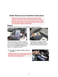
2 THE AIR BAG SYSTEM IS A SENSITIVE AND COMPLEXELECTRO-MECHANICAL UNIT. BEFORE BEGINNING THISINSTALLATION YOU MUST FIRST DISCONNECT ANDISOLATE THE NEGATIVE BATTERY CABLE (GROUND).AFTER DISCONNECTING THE NEGATIVE BATTERY CABLE,WAIT AT LEAST ONE MINUTE BEFORE CONTINUING TOWORK ON THE VEHICLE. FAILURE TO DO SO COULDRESULT IN ACCIDENTAL DEPLOYMENT OF THE AIR BAGAND POSSIBLE PERSONAL INJURY. THE FASTENERS,SCREWS, AND BOLTS ORIGINALLY USED FOR THE AIRBAG COMPONENTS HAVE SPECIAL COATINGS AND ARESPECIFICALLY DESIGNED FOR THE AIR BAG MUST NEVER BE REPLACED WITH ANYSUBSTITUTES. ANY TIME A NEW FASTENER IS NEEDED,REPLACE WITH THE CORRECT FASTENERS PROVIDEDIN THE SERVICE PACKAGE OR FASTENERS LISTED INTHE PARTS BOOKS. SAFETY GLASSES SHOULD BE WORNAT ALL device complies with FCC rules part 15. Operation is subject to thefollowing two conditions: (1) this device may not cause harmful interferenceand (2) this device must accept any interference that may cause or modifications not expressly approved by the party responsiblefor compliance could void the user s authority to operate the InstallerPreparationPage 45.
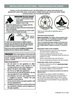
3 AlarmConnectionsPage 86. SystemPower-Up, Test,and AdjustmentPage 11 Installation FlowchartMainPowerMainGroundCourtesyLigh tsPower DoorLocksHeadlampsParking LampsSiren(Optionalw/Keyless)OverrideBut tonShockSensor SystemPower-UpTestingandAdjustmentSystem ProgramProcedureOwner sManual Security and Keyless SystemsOptionalKeyless Entry Only2. VehiclePreparationPage 53. Main HarnessConnectionPage 64. SecondaryHarnessConnectionsPage 7 StarterInterrupt (SecurityOnly)SwitchedPowerStatusIndicat or /Pushbutton41. Installer PreparationA. Required Tools:B. Connection ProceduresRemove and Replace ProcedureTerminal extracting toolNeedle nose pliersAcid free solder (rosin core)T-15, T-20 & T-30 TorxscrewdriversWire cutter/strippersAssorted ScrewdriversAssorted Nut driversVoltmeterSoldering ironCenter Splice ProcedureStrip and Splice ProcedureLocate the the the the appropriatewire(s) by releasing thetang inside the connectorwith a terminal the appropriateEVS wire into thecavity.
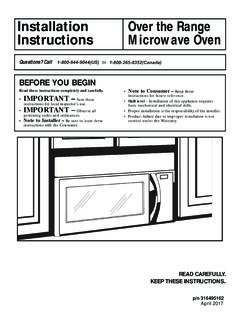
4 Replace thelocking the two connectorsback the vehicle wire intothe appropriate cavity onthe EVS the locking wedgeinto the EVS connectorand plug the two matingEVS connectors back the and solder EVS wireonto the exposed with a minimum 4wraps of back insulation 1/2 from both and solder each wireto EVS wire splice with tapeor heat shrink Vehicle PreparationA. Pre Installation1. Lower the driver s door window to avoid locking the keys in the vehicle and isolate the negative battery fuse from the EVS wiring the System Layout at the back if this Interior the knee blocker the lower halves of the steering column shroud. There are five (5) T-20 torx screws in the bottom of the shroud holding it in Main Harness ConnectionReplace Ignition Switch Harness with EVSP ower the 7-way ignition switch connectorfrom the back of the ignition switch ( ).
5 Carefully slice back harness tape so that7-way ignition connector can be freely pulledabout half way down the steering : Be careful not to slice or pull on theairbag harness. This is the thin black shrinktubed the EVS power harness connector A (seediagram ) into the vehicle ignition the vehicle's original 7-way ignition switch connector into connector B onthe EVS power the ignition switch wiring harness assembly to the other steeringcolumn wiring harnesses using the supplied long tie wraps. Make sure to routeharness so that the EVS 6-way module connector is near the base of thesteering POWERHARNESSDIAGRAM Secondary Harness Connection(s)A. Courtesy Light the C203 26-way body connector(Diagram ) attached to the bottom ofthe 74-way instrument panel connector(left side of steering column). splice the EVS YELLOW wire tothe M2 YL wire in cavity #8 of the 26-way body Ground a solid metal body panel or dashbracket that is the targeted ground point with one of the supplied sheet metalscrews to attach the ground lug to theverified ground point (DIagram ).
6 Usecare not to over-tighten this screw. Coverthe connection point with a small amountof non-conductive grease or rust-inhibitingpaint to prevent future Door Lock Harness1. Pull back the vehicle side of the driver's doorjamb boot to expose the 16-way connector(Diagram ). Remove the interior driver's kick panel and pullthe vehicle side of the 16-way connector into thevehicle. Plug the mating 16-way connector fromthe EVS wire harness onto the vehicle-side16-way Route the remaining EVS 16-way connector outof the door jamb hole. Plug into the door-sidevehicle 16-way Replace the door jamb boot, ensuring that it isproperly Headlamps / Parking LampsNote: An optional Headlamp / Parking Lamp kit is required for these this Installation is to include the Headlamp Illumination and Flashing Parking Lightoption, do that Installation now.
7 Follow the Instructions supplied with the body panelDiagram Alarm ConnectionsA. Siren (Optional w/ Keyless Entry) the mounting location, just behind the battery on the drivers side fenderwell (see picture ). the siren using the supplied 1/4' sheet metal the siren wires to the area where the hood release cable goes through thebulkhead the inside of the vehicle, pop out hoodlock release cable the siren wire harness through hoodlock release cable grommet inside thevehicle (use care not to damage the terminals on the end of the siren wires). the hood release cable grommet. It may be necessary to slit thegrommet to properly seat it back in the firewall. Use a small amount of silicone, ifnecessary to completely reseal the siren wires into the 22 waymodule RED into cavity # BLACK into cavity # from wire endPICTURE Alarm ConnectionsB.
8 Multi-Function Status Indicator / Entry Systems: Find a mounting location under the dash that is noteasily seen, yet is accessible by the Systems: Find a mounting location for the status indicator that is visiblefrom outside the Make sure that there is at least 2" clearance behind the selected mountinglocation and any vehicle Drill a 5/16" mounting hole. Then, using a small file notch the mounting hole toaccommodate the key way on the switch Feed the status indicator wires through the mounting hole and snap the switchbody firmly into the hole. Depress the switch a few times to ensure that it travelsfreely. If necessary, carefully enlargethe If necessary, slide the retaining ringover the back of the switch Insert the status indicator wires into the22-way module connector:Security BLUE wire into cavity # GREEN wire into cavity # ORANGE wire into cavity # Entry BLUE wire into cavity # GREEN wire into cavity # ORANGE wire into cavity # BROWN wire into cavity # FROM WIRE END OF CONNECTORVIEWED FROM WIRE END OF CONNECTORS tatus Indicator Connection - SecurityStatus Indicator Connection - Keyless Entry105.
9 Alarm ConnectionsC. Emergency Override / Programming Button (Security Only)1. Find a hidden (not plainly visible) location underdash that is accessible whilesitting in the drivers seat. It is suggested that the override button be mounted in adifferent location for each Drill a 5/16" mounting hole and mountthe disarm Insert the BROWN disarm button wiresinto cavities #2 & 13. The disarm buttonwires are Shock Sensor (Security Only)1. Find a mounting location for the shocksensor. The sensor must adhere to asurface (or wire harness) under theinstrument panel that is in solid contactwith the vehicle chassis. The Ignitionswitch wiring harness is an excellentchoice. Be sure to mount the shocksensor so that the can be viewedwhen adjusting the Stick one of the supplied squares ofadhesive tape to the bottom of theshock sensor case.
10 Then attach thesensor to mounting surface. Use one ofthe supplied long tie wraps to securesensor firmly in Insert the shock sensor wires into the22-way module wire into cavity # wire into cavity # wire into cavity # wire into cavity # FROM WIRE END OF CONNECTORVIEWED FROM WIRE END OF CONNECTOR116. System Power-Up, Test, and AdjustmentA. System Power-Up1. Re-check all connections and connectors to make sure they are properlyinsulated and seated with their appropriate mating Re-connect the vehicles negative battery Replace any vehicle fuses removed during the Plug the 6-way (power), 8-way (door lock) and 22-way (accessory) harnessesinto the EVS Turn the ignition key to the ON Replace the module power fuse on the 6-way Turn the ignition key Replace the door lock fuse on the 8-way System TestBefore testing the system operation, make sure to roll the drivers door window any of the following items fail to function properly, refer to the appropriate section inthe Installation manual and double check all wiring, connector pin outs and replacing the module or any of the systems components, contact technicalservice at the number listed on the front cover of this : The items below that are underlined apply only the EVS Security system.