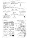
Transcription of Installation Instructions for Eave Application
1 Cutting the 1 1/2" Vent Slot Opening Step 1: Install drip edge along the eave per local code 2: Chalk a line from rake edge to rake edge that is 6 1/2" above the lower edge of the drip edge or eave 3: Chalk an additional line, 1 1/2" above this line. These lines will identify the top and bottom edges of the vent slot 4: Make marks on the roof 6" in from the gable end wall at each rake edge. The marks will identify the ends of the vent slot Figure the 1 1/2" Vent Slot Opening (Continued) Note: The vent slot opening must stop 6" from chimneys, end walls, vertical walls, or other obstructions, and a minimum of 24" from roof valleys. See Figure 5: Using a circular saw with the depth set to the thickness of the roof deck, cut and remove all materials from the area identi ed for the vent slot opening.
2 Note: To provide full ventilation, be sure to maintain at least 1" of clearance between the attic insulation and the bottom of the roof the VentStep 7: Position the first InFlow Vent flush with the rake edge, aligning the vent so the alignment notch is even with the eave edge. This will ensure the vent overhangs the eave edge by 1", allowing air intake through the bottom of the InFlow Vent. See Figure Underlayment beneath the InFlow VentStep 6: Install a minimum 18" wide piece of underlayment starting at the eave edge. This will cover the slot opening and protect the roof deck below the vent. Identify where the slot opening is underneath the underlayment and cut out the 1 1/2" slot using a sharp utility knife.
3 See Figure 8: Using the nails provided, hand-nail InFlow Vents in place using the built-in nail holes. Continue installing vents flush with each other from rake edge to rake edge. When installing the final vent, cut the non-rake edge of the vent (if necessary), to ensure a factory-finished edge is flush with the rake edge. See Figure 11: Hand nail the starter and roofing shingles on top of the vent using the 3" nails provided. See Figures 6 and : Be sure that all nails fully penetrate the wood deck and do not fall within the vent slot opening. Consult your shingle manufacturer for recommendations as 12. Continue shingle system Installation per manufacturer s specifications. Note: A nail gun and standard roofing nails can be used to install shingle courses above the InFlow Vent, per shingle manufacturer s Installation conditions which are not addressed by these Instructions , please contact us at 1-800-GET-PINK (1-800-438-7465) or visit for further Instructions .
4 installing Remaining Shingles & UnderlaymentStep 9: Once the InFlow Vents are installed across the roof, install an underlayment or WeatherLock Ice & Water Barrier over all vents, at the eave, and at the rake edges per local code requirements. Ensure the bottom edge of the underlayment is flush with the lip at the lower edge of the vent, completely covering the top intake openings. IMPORTANT: The InFlow Vent s top intake openings must be completely covered, as air intake occurs through the bottom of the vent with an eave Figure 6 and 7. Note: In cold climates where code requires the use of an ice and water barrier, it must extend 24" above the exterior wall. It may be necessary to install a second course of an ice and water barrier to meet this code 10.
5 Finish installing an approved underlayment over the entire roof, per shingle manufacturer s Instructions . Once the underlayment is in place, install rake edge metal over the entire rake, including the InFlow : Rake edge metal with a 1 1/4" minimum vertical leg will completely conceal the factory-finished edge of the InFlow foot STRIP INFLOW VENTVENTSURE Installation Instructions for Eave Application (See separate sheet for Mid-Roof Application )The following Instructions are to be used when installing the VentSure InFlow Vent at the eave of the Note Please review the following Instructions thoroughly before beginning your Eave InFlow Vent ApplicationPrimary Intake on Cape Cod or Other Sof t-less HomesTypical Eave InFlow Vent ApplicationSupplemental Intake on Sof t Homes which are Under-ventilated or where Intake is BlockedOWENS CORNING ROOFING AND ASPHALT, LLCONE OWENS CORNING PARKWAYTOLEDO, OHIO 43659 Copyright 2014 Owens Corning.
6 All Rights No. 10018103-CFigure 1 Figure 4 Figure 26" " 1/2" Vent slotopening6 1/2" From drip edgeor eave edgeRakeoverhangGableendwall6" 24" 24" min. from valley 1 1/2" slot18" Minimumunderlayment beneath ventInFlow Vent1" OverhangVentalignmentnotchDrip edgeFigure 6 Underlayment over the ventas code requiresInFlow VentFigure 5 UnderlaymentHand nail shingleon top of ventHand nail starterFactory edgeFactory edgeCut edgeCover the InFlow Venttop intakeUnderlaymentHand nail shingleon top of ventHand nail starterCover the InFlow Venttop intakeDrip edge belowUnderlayment1 1/2" Vent slotUnderlayment1 1/2" Vent slotFigure 71 1/2"Vent slot6 1/ 2"Eave edgeto bottomof slotDrip edge6" minimuminside gableend wallCut & removematerial6" minimuminside gableend wallCut & removematerialFigure 31 1/2"Vent slotMinimum18"underlaymentDrip edgeCut &
7 RemovematerialCut & removematerialAddInFlow Vent(Exhaust ventilation)Precautionary Notes:Before installing this product, check local building codes for their roo ng and ventilation requirements. This vent is designed for new or re-roo ng work over any properly built and supported wood roof deck having adequate nail-holding capacity and a clean, smooth surface. The InFlow Vent is designed for roof slopes 4:12 or greater. The manufacturer will not be responsible for issues resulting from any deviation from the recommended Application Instructions and the following precautions:Roof Deck Maximum 6" width and 25/32" minimum thickness wood sheathing Minimum 3/8" plywood sheathing or 7/16" OSB Sheathing spaced minimum 1/8" and decking spaced maximum 1/4" Check local building codes or decking recommended by APAV entilation Must comply with local building code The InFlow Vent is packaged with 3" ring shank nails to be used when installing the vent and any roo ng materials installed directly on the vent.
8 Follow roof covering manufacturer's guidelines and local code requirements for all other and materials required to install a VentSure InFlow Vent: Utility knife Tape measure Circular saw Hammer 3" Hand Nails (provided with the vent) Chalk line Underlayment/self-adhering membrane Drip edge (for eave) Starter and Roo ng Shingles Rake edge metal (minimum 1 1/4" vertical leg)(Exhaust ventilation)AddInFlow Ve ntAddInFlow VentAddInFlow Ve ntAIRAIRAIR3" Handnails providedfor starter and shinglesover (1-800-438-7465)Drip edgeCorte de la abertura de la ranura de ventilaci n de 1 1/2 pulg.
9 Paso 1: Instale el borde de goteo a lo largo del alero, seg n los requisitos del c digo de construcci n 2: Marque una l nea de tiza desde la cornisa del t mpano que est 6 1/2 pulg. por encima de la parte inferior del borde de goteo o borde del 3: Marque una l nea adicional con tiza, 1 1/2 pulg. arriba de esta l nea. Mediante estas l neas se identi car n los bordes superior e inferior de la abertura de la ranura de la ventilaci 4: Haga marcas en el techo 6 pulg. hacia adentro desde la pared extrema del hastial en cada cornisa de t mpano. Mediante estas l neas se identi car n los extremos de la abertura de la ranura de la ventilaci n. Consulte la gura de la abertura de la ranura de la ventilaci n de 1 1/2 pulg.
10 (continuaci n)Nota: La abertura de la ranura de la ventilaci n debe terminar a 6 pulg. de chimeneas, paredes extremas, paredes verticales u otras obstrucciones y a un m nimo de 24 pulg. de las limahoyas del la gura 5: Use una sierra circular con la profundidad con gurada seg n el espesor de la plataforma del techo para cortar y quitar todos los materiales del rea identi cada para la abertura de la ranura de la ventilaci : Para que la ventilaci n sea completa, aseg rese de mantener un espacio m nimo de 1 pulg. entre el aislamiento del tico y la parte inferior de la plataforma del n de la ventilaci nPaso 7: Coloque la primera ventilaci n InFlow al ras con el borde de la cornisa del t mpano y alinee la ventilaci n de modo que la ranura de alineaci n est nivelada con el borde del alero.