Transcription of Installation Instructions Part Numbers - Reese
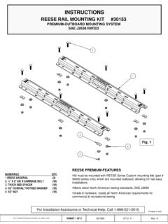
1 26&718 Installation InstructionsREESE Dual Cam HPHigh-Performance Sway ControlPart Numbers :26002 2014 , 2017 HORIZON GLOBALS heet 1 of 3326002IN5/31/17 Rev. TQty. (2)Dual Cam HP Cam Arm AssemblyQty. (2)Hanger Bracket Snap up BracketQty. (2) -13 Thread Forming Screw (Optional use with snap up Bracket. Not Shown Here.)Qty. (2) -13 X 3 Square Head BoltQty. (6) -13 Hex NutQty. (4) Lock WasherQty. (4) -13 X 1 Grade 5 BoltQty. (4)Rivet NutsDo Not Exceed Lower of Towing Vehicle Manufacturer s Rating, or Trailer Manufacturer s RatingDEALER/INSTALLER:(1) Provide this Manual to end userEND USER:(1) Read and follow this Manual every time you use Dual Cam HP.(2) Save this Manual for Future Reference.(3) Pass on copies of Manual to any other users or :Failure to follow all of these Instructions may result in death or serious injury!Figure 1 DUAL CAM HP ASSEMBLEDE quipment Required:Wrenches:1-1/2 Open End, Open EndDrill Bits:7/16 , 17/32 & Center Drill (Pilot Drill)Fastener Kit:100126 Open End, Socket & RatchetOther:8 10 C-Clamp, Tape Measure, Light Penetrant OilFor Installation or Operation Support contact CPP Technical Service: 1-800-632-3290 Figure 2 Inside View of Trailer Frame 54 STEEL trailer frames only.
2 Not for use with aluminum frames. ADJUSTMENT NUTLOCK WASHERYOKELOCK NUT 2014 , 2017 HORIZON GLOBALS heet 2 of 3326002IN5/31/17 Rev. TINSTALLATIONF igure 31. Locate both hanger brackets included in the kit (item 2, figure 1). Install U-bolt and chain from your Weight Distribution Kit on each hanger bracket as shown in figure 3 (if installing Dual Cam HP on an existing weight distribution kit, the U-bolts and chains will need to be removed from each spring bar before they can be installed on the hanger brackets).The U-bolts must be installed in the ends of the chains (last link) as shown in figure 3. Installation InstructionsREESE Dual Cam HPHigh-Performance Sway Control2. Install 2 lock nuts per U-bolt, tighten u-bolt nuts. Make sure at least 2 threads are showing past the ends of the If the adjustment is difficult, as the adjustment nut must be turned by hand, apply a small amount of light penetrating oil such as WD40 or PB Blast to the threads of the cam arm.
3 Work the adjustment nut back or forward to get the penetrating oil into the threads until the adjustment nut moves freely to the desired position. 3. Using a grease pencil or suitable marking device such as a marker and a straight edge locate and mark the center of the hitch ball on the coupler both horizontally and vertically as shown in figure 4 . This reference point will be used to locate thecam arm assembly position. Mark bothsides of the 4 Figure 5 2014 , 2017 HORIZON GLOBALS heet 3 of 3326002IN5/31/17 Rev. TThe Measurements in figures 6, 6A, 7 & 7A are guidelines , adjustment of the cam arm length via the adjustment nut (Figure 5) may be required after hookup in later Instructions of this manual Cequent Performance Products, Inc. is not responsible for damage incurred due to disregarding any part of this manual.
4 CAUTION:5. Using a C-clamp suitable to accommodate your trailer frame height and the Dual Cam HP frame plate, temporarily clamp the Dual Cam HP cam arm assembly to the trailer frame and Dual Cam HP frame plate as shown in figure 6 for Trunnion style Weight Distribution kits, for Round Bar style Weight Distribution Kits, follow the dimensions in figure 7. 6. Position the Frame Plate at the dimension shown for your type Weight Distribution Kit (Trunnion Style or Round Bar. Standard coupler or bottom mounted). Measure from the mark on the ball coupler to the center of the cam arm pivot bolt as shown in figure 6 or figure 7 on the next page. If the frame plate interferes with any part of the trailer frame, the orientation can be changed by switching sides, see figure 10 for optional Frame plate orientation maintain the same coupler center to cam arm pivot dimension regardless of frame plate orientation. 7. Position the Chain Hanger temporarily above the cam arm.
5 (Upon hook-up, the Hanger position must be adjusted to be sure the chain is vertical before towing). Tighten the Chain Hanger bolt shown in figure 2 against the 6 Installation InstructionsREESE Dual Cam HPHigh-Performance Sway ControlTrunnion Style Set Up Locations(Standard Coupler) you have a bottom mounted coupler it may be necessary for you to tilt the ball mount as far forward towards the front of the tow vehicle as 6A20-1/2 FROM MARK ON COUPLERALONG SIDE FRAMET runnion Style Set Up Locations(Bottom Mounted Coupler)Approximate desired working range on a 6 tall -13 Approximate desired working range on a 6 tall -13 19-3/8 2014 , 2017 HORIZON GLOBALS heet 4 of 3326002IN5/31/17 Rev. TThe Measurements in figures 6, 6A, 7 & 7A are guidelines , adjustment of the cam arm length via the adjustment nut (Figure 5) may be required after hookup in later Instructions of this manual Cequent Performance Products, Inc.
6 Is not responsible for damage incurred due to disregarding any part of this manual. CAUTION:If you have a bottom mounted coupler it may be necessary to tilt the ball mount as far forward towards the front of the tow vehicle as 7 AREESE Dual Cam HPHigh-Performance Sway ControlInstallation Instructions19-1/8 FROM MARK ON COUPLERALONG SIDE OF FRAMEF igure 7 Round Bar Set Up Locations(Standard Coupler)Round Bar Set up Locations(Bottom Mounted Coupler)Approximate desired working range on a 6 tall -13 Approximate desired working range on a 6 tall -13 18 Rivet nuts hex head bolts with lock washersLong boltDirections for installing the rivet nut in a Tube the dual cam bracket on the frame at the correct spot for your Installation . the long bolt to clamp the bracket in position, with C-clamp still in place. the holes in the bracket as a guide, drill two 7/16 holes into the the bracket and drill the holes out to 11/16.
7 Do not ream out the hole. This needs to be a snug the Rivet Nuts into the holes in the the bracket over the rivet nuts, thread the -13 x 1-1/2 hex head bolts with lock washers into the holes. the long bolt against the frame, turn after contact with the the bolts on the outside of the frame. to 75 ft. Nut 2014 , 2017 HORIZON GLOBALS heet 5 of 3326002IN5/31/17 Rev. TCAUTION:Before drilling, make sure there are no obstructions in the trailer frame where the intended bolt holes are to be drilled, suchas trailer wiring and/or electric brake breakaway switch. 2014, 2017 HORIZON GLOBALS heet 6 of 3326002IN5/31/17 Rev. TInstallation InstructionsREESE Dual Cam HPHigh-Performance Sway ControlC-CHANNEL DUAL CAM HP FRAME PLATE INSTALLATIONNOTE: Some C-Channel frames may have square outside corners that do not allow the frame plate to contact the bottom of the frame. For these type of frames a flat washer (Not Supplied) is required between the outside of the trailer frame and the frame plate.
8 The bottom of the frame plate MUST contact the bottom of the trailer the C-clamps still in place, center punch (2) holes in the frame for each bracket. (2) 17/32 holes in each side of the frame where the punched center marks were made. The use of a center drill or small pilot hole may be very helpful prior to final the (2) supplied -13 x 1 Bolts, Lock Washers & Nuts (items 5,6 & 7) figure for opposite side and torque (4) -13 Bolts to 85 -13 Hex Nuts onto the -13 X 3 Square Head Bolts and install into the frame brackets as shown in figure the Set Screw until it contacts the trailer frame. Then proceed to tighten to turn (DO NOT OVERTIGHTEN SET SCREW). Tighten the Jam Nut preventing the set screw from backing out while in use. Repeat for other side of trailer C-Clamps from 9 SET SCREWJAM NUTNUTLOCK WASHERHEX HEAD BOLT 2014, 2017 HORIZON GLOBALS heet 7 of 3326002IN5/31/17 Rev.
9 TInstallation InstructionsREESE Dual Cam HPHigh-Performance Sway ControlFigure 10 PRE- Installation (TOW VEHICLE MAY NOT BE PRESENT)1. If the tow vehicle is not available at the time of Installation of the Dual Cam HP system, position the yoke centered on the threads of the cam arm (Approximately 2 from either end of the threaded portion of the cam arm. Run the adjustment nut down to meet the yolk. Tighten the locking nut until the lock washer is fully compressed and continue to the Frame Plate Installation portion of this manual for your specific frame style; Tubular Frame or C-Channel Pass this manual along to the customer/end user of this product and inform them that minor adjustments to their cam arm length may be required depending on head tilt of the WD system, number of chains used for proper weight distribution, tow vehicle variance and/or; changes in tongue weight of their trailer as all of these variables will slightly affect the proper position of the cam with respect to proper seating in the detent of the cam Direct the customer to the Installation WITH TOW VEHICLE PRESENT portion of this manual for hook-up procedure, and fully explain proper seating of the cam within the spring bar detent.)
10 Refer them to their specific Weight DistributingHitch Instruction manual and be sure they follow the INITIAL HOOKUP section of their Weight Distribution Kit Manual for first time hook-up and/or any changes in the variables listed in item 2. of this section BE SURE to pass along the Towing Information Packet (P/N: 110400) to the customer/end user and BE SURE they understand the material within the Towing Information Packet for safe towing. Installation WITH TOW VEHICLE PRESENTNOTE: Set-up and adjust weight distribution hitch per the Installation Instructions for your Weight Distribution Connect the trailer to the tow vehicle. Tow vehicle and trailer should be on level ground and in a straight line. Raisethe tongue and rear of the vehicle enough to install the spring bars onto the dual cam arm with the trailer tongue jack (approximately 6 -12 or until the spring bar can be lifted with the supplied lifting handle with very little effort, this will vary depending on spring bar rating and head tilt adjustment).