Transcription of SYNC CONTROL SET UP TROUBLE SHOOTING GUIDE
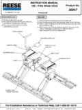
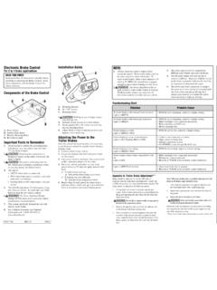
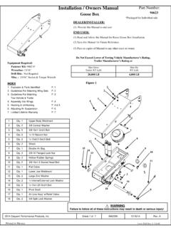
1 + sync -OUTPUTACTIVATOROUTPUTACTIVATOROUTPUTCON TROLMore Output Less OutputOUTPUTINDICATORSYNC CONTROLMANUALCONTROLMore Aggressive Braking Less Aggressive BrakingPush to ApplyTrailer BrakesCONTROLS OUTPUT CONTROLThe output CONTROL is located on the front of the brakecontrol unit at the top left output CONTROL establishes the maximum amount ofpower available to the trailer the setting is moved to the left more power will beavailable to the brakes when the brake pedal ispressed or the manual CONTROL is output CONTROL would be adjusted when trailer loadchanges, when different trailers are used or to adjustfor a change in road CONTROLThe sync CONTROL is located on the left side of the brakecontrol unit, forward of the mounting bracket. The synccontrol adjusts brake aggressiveness or the time it takesto reach the full output set by the output CONTROL when thebrake pedal is sync adjustment has no effect on the manual brakes become more aggressive as the switch ismoved toward the front of the tow sync CONTROL would be adjusted for individual driverpreference or changing road CONTROLThe manual CONTROL is located on the front of the brakecontrol unit at the right manual CONTROL only applies the trailer brakes andwould be used in situations when it is desirable to reducespeed the manual CONTROL is pushed to the left the controlbegins to apply the trailer brakes.
2 The further to the left itis pushed the harder the brakes are applied until themaximum set by the output CONTROL is manual CONTROL activates the tow vehicle and trailerstoplights and the output indicator on the CONTROL INDICATORThe red indicator light on the front of the CONTROL unit willglow when brakes are applied either by the brake pedalor the manual CONTROL (with or without a trailer attached).The indicator will start dim and glow brighter as indicator light will also help confirm proper UP1. With a trailer connected, set the sync CONTROL halfway between + and -. Starting with the outputcontrol in the lowest position (all the way right) rollforward slowly and stop. If no trailer braking is feltadjust the output CONTROL slightly to the left. Repeatthis process until firm trailer brakes are felt.
3 If thetrailer brakes lock-up or jerk adjust the outputback to the right Move the sync CONTROL back (toward the driver) toabout 1/4 of the distance between + and Test drive making several stops. Adjust the synccontrol until stops are smooth and firm. Slightadjustment of the output CONTROL may also the brake CONTROL too aggressivelycould cause brake pulsing when towingwith hazard flashers on. If such settingsare necessary, a pulse preventor can Have someone watch the stoplights while themanual CONTROL is activated to make sure the stop-lights on both the tow vehicle and trailer are : If any problems occur during set up refer tothe TROUBLE SHOOTING section of these TIPSL ight pressure on the brake pedal will activate thetrailer s brakes with little or no effect on the tow vehi-cle s brakes.
4 This is useful for gradual slowing onsteep downhill grades or before stops. INSTRUCTIONS FOR THE INSTALLATIONAND OPERATION OFELECTRONIC TRAILER BRAKE CONTROL FOR 2 AND 4 BRAKE SYSTEMSIMP0 RTANT: READ ANDFOLLOW THESEINSTRUCTIONS CARE-FULLY. KEEP THESEINSTRUCTIONS IN YOURTOW VEHICLE FORFUTURE PACKAGE INCLUDES:(1) Brake CONTROL Unit(1) Mounting Bracket(4) Mounting Screws(1) Wire Tap Connector(1) Warranty CardTOOLS REQUIRED:Assorted end wrenchesDrill with 1/8 bitWire connector crimp toolProbe type circuit testerWire cutter/stripperScrewdriverMATERIAL REQUIRED:12 Ga. or larger wire20 Amp auto-reset circuit breakerAssorted ring terminals & butt connectors4 cable ties (6-10)+ sync Periodic adjustment of the sync and Output con-trols may be necessary to correct for changing roadconditions, trailer loading, brake wear and/or some vehicles, operating the brake CONTROL s manualcontrol will not disengage Cruise CONTROL .
5 TROUBLE SHOOTING GUIDEPROBLEMLIGHTPOSSIBLE CAUSESSOLUTIONTRAILER BRAKING IS DELAYEDONINCORRECT sync ADJUSTMENTADJUST TO MORE AGGRESSIVE POSITIONTRAILER BRAKES COME ON TOO FASTONINCORRECT sync ADJUSTMENTADJUST TO LESS AGGRESSIVE POSITIONTRAILER BRAKES ARE WEAKONINCORRECT OUTPUT ADJUSTMENTADJUST FOR MORE OUTPUTTRAILER BRAKES COME ON TOO HARDONINCORRECT OUTPUT ADJUSTMENTADJUST FOR LESS OUTPUTNO TRAILER BRAKES - PEDAL OR MANUALOFFNO POWER TO UNIT THRU BLACK BATTERY + WlRE CHECK CONNECTIONS AT: BATTERY,OPERATIONCIRCUIT BREAKER, BRAKE CONTROLOUTPUT ADJUSTED TOO LOWRE-ADJUST (SEE SET UP)NO TRAILER BRAKES - PEDAL OR MANUALONNO CONNECTION TO TRAILER BRAKES THRU BLUECHECK TRAILER CONNECTOR CONTACTSOPERATION(BRIGHT) BRAKE WIRECHECK WIRE CONNECTIONS (SEE WIRlNG)TRAILER OR TRAILER BRAKES NOT GROUNDEDCHECK TRAILER AND BRAKE GROUNDSNO TRAILER BRAKES USING BRAKE PEDALOFFNO CONNECTION AT STOPLIGHT SWITCH THRU REDCHECK STOPLIGHT CONNECTIONMANUAL OPERATION WORKS(PEDAL) STOPLIGHT WIRE(SEE WIRlNG STEP 8)ON(MANUAL)TRAILER BRAKES LOCKED ON WHENRED STOPLIGHT WlRE CONNECTED TO WRONGCHECK CONNECTION (SEE WIRlNG STEP 8)
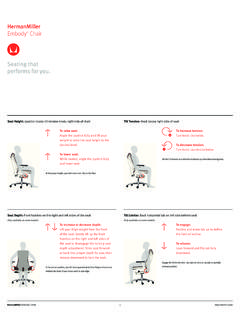
6 CONNECTED TO CONTROLONSIDE OF STOPLIGHT SWITCH OR TO BATTERY +BREAK-AWAY SWITCH ACTIVATEDCHECK SWITCH AND CORRECTTRAILER BRAKES SEEM TO BE WORKINGDIM ORFAULTY WHITE GROUND WIRE CONNECTIONCHECK CONNECTIONSFLICKERSWEAK OR INCONSISTANT TRAILER BRAKESDIM ORSHORT IN BLUE BRAKE WlRE CIRCUITLOCATE SHORT & CORRECTFLICKERS SHORT IN TRAILER BRAKE CIRCUITLOCATE SHORT & REPAIRBRAKE CONTROL OVERHEATS, SMELLSDIM BLACK BATTERY + WIRE & WHITE GROUND BRAKE CONTROL UNIT DESTROYEDHOT, LOW OR NO BRAKE OUTPUTWIRE CONNECTIONS REVERSEDCORRECT WIRING & REPLACE UNITTOWING PRODUCTS 47774 Anchor Court WestPlymouth, MI 48170 TOWING PRODUCTS 2003 PRINTED IN CHINA05100-037 1 of 3 rev. 1/21/03 Note:A standard voltmeter will not show true output 1/21/03 English 3/6/03 2:00 PM Page 112 Volt Tow Vehicle BatteryBATTAUX20A Auto-ResetCircuit Breaker(Not Supplied)This Electronic Brake CONTROL is for Use on 12-Volt Negative Ground Systems OnlyIMPORTANT: DO NOTREVERSE BLACK AND WHITE WIRE CONNECTIONS!
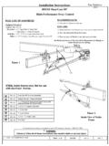
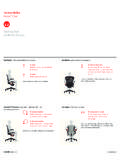
7 Damage to the brake CONTROL unit will occur!IMPORTANT: Read andfollow all warnings and cautions printed on tow vehicle INSTRUCTIONS: For Ford E and F Series Trucks and Vans, 1989-1991 with Anti-Lock Brakes Do NOT Connect to stoplight switch on these vehiclesTurn signal harness connector underdash near steering column. Splice red stoplight wire to light green wire using the wire tap connector suppliedLightGreen WireTrailer ConnectorBrake ControlBattery (+) BlackStoplight RedGround ( ) WhiteBrake BlueWire Tap(Supplied) Use 12 gaugeor larger wireButt Connectors(Not Supplied)StoplightSwitchConnect to cold side ( On only when brake pedal is depressed), see wiring Step 8. IMPORTANT: For 1989-1991 Ford E and F Series vehicles with anti-lock brakes see Step 8 and special instructions above.+ sync -UNDER DASH + sync -ANY ANGLEVERTICAL+ sync -TOP OF DASHIMPORTANT: Make sure area behind panel is clear before drilling!
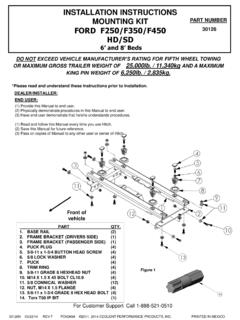
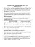
8 OUTPUTACTIVATORUse bracket as template to mark hole two 1/8" diameter holes and mount bracket with screws brake CONTROL to bracket using the remaining two and crimp type ring terminals connect the BATT side of the circuit breaker to the positivebattery Feed two, different colored, 12 GA or largerstranded wires from the brake CONTROL location tothe tow vehicle battery Connect one of the wires (noting the color) to the AUX side of the circuit breaker with a ring Connect the other wire to the negative batterycable with a ring Attach the CONTROL s black BATTERY + wire to thewire connected to the AUX terminal of the circuitbreaker using a butt connector. Make sure that theconnection is made to the correct wire (color).7. Connect the CONTROL s white GROUND - wire tothe wire leading to the negative side of the batterywith another butt : A brake CONTROL that is not properlygrounded may operate intermittently or not at sure all connections are For tow vehicles other than 1989-91 Ford E and Fseries trucks and vans:Determine which side of the stoplight switch is thecold side.
9 To determine the cold side probe theterminals of the switch with a test light until one isfound that is only on when the brake pedal the wire tap provided, splice the brake CONTROL sred STOPLIGHT wire to the wire attached to the coldside of the stoplight switch as determined 1989-91 Ford E and F series trucks and vanswith anti-lock brakes:Find the crescent shaped connector located on thesteering column (turn signal harness). The connectorhas two rows of wires, one row has four wires (insiderow) the other has seven. The wire needed is the lightgreen wire, second from the left in the row of seven(see wiring diagram).Using the wire tap provided, splice the brake CONTROL sred STOPLIGHT wire to the light green wire. 10. Secure all loose wires with cable ties so that they willnot be damaged and reconnect battery.
10 See vehicle sowners manual for special reconnection TEST INSTRUCTIONS1. Wire as shown at right. Set Output CONTROL to maxi-mum and the sync CONTROL to Test brake pedal activation:While watching the test bulb, hold the red wire on thepositive (+) battery terminal. The bulb should start dim and slowly get red output indicator on the brake CONTROL shouldglow the red the sync CONTROL to maximum (+).While watching the test bulb, hold the red wire on thepositive (+) battery bulb should light brightly with no the red wire still on the battery terminal, slide theoutput CONTROL back and forth. The test bulb shouldchange from bright to dim with the movement of theoutput CONTROL . Disconnect the red Test manual activation:Set the output CONTROL to watching the test bulb, slowly activate themanual test bulb should start dim and get brighter asthe manual CONTROL is holding the manual CONTROL all the way on,slide the output CONTROL back and forth.