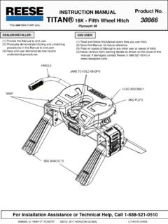
Transcription of Installation / Owners Manual Part Number
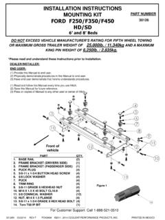
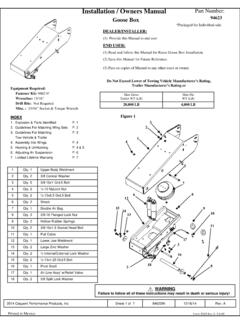
1 Installation / Owners Manual Goose Box part Number : 94621 94622* *Packaged for Individual sale. Equipment Required: Wrenches: 15/16 Drill Bits: Not Required Misc. : 15/16 Socket & Torque Wrench INDEX 1. Explosion & Parts Identified P. 1 2. Guidelines For Matching Wing Sets P. 2 3. Guidelines For Matching P. 3 Tow Vehicle & Trailer 4. Assembly Into Wings P. 4 5. Hooking & UnHooking P. 4 & 5 6. Adjusting Air Suspension P. 6 7. 5 Year Limited Warranty P. 7 2009 Cequent Performance Products, Inc Sheet 1 of 7 94621IN 3/6/2012 Rev. C 1 Qty. 1 Upper Body Weldment 2 Qty. 2 3/8 Conical Washer 3 Qty. 5 3/8-16x1 Bolt 4 Qty. 2 -13 NyLock Nut 5 Qty. 2 Bolt 6 Qty. 2 Shock 7 Qty. 1 Double Air Bag 8 Qty. 3 3/8-16 Flanged Lock Nut 9 Qty. 2 Hollow Rubber Springs 10 Qty. 2 3 Socket Head Bolt 11 Qty. 1 Pull Cable 12 Qty.
2 1 Lower Jaw Weldment 13 Qty. 2 Large Zinc Washer 14 Qty. 2 Internal/External Lock Washer 15 Qty. 2 Bolt 16 Qty. 1 Pivot Shaft 17 Qty. 1 Air Line Assy w/Relief Valve 18 Qty. 2 3/8 Split Lock Washer Fastener Kit: 94621F Do Not Exceed Lower of Towing Vehicle Manufacturer s Rating, Trailer Manufacturer s Rating or Max Gross Trailer WT (LB) Max Pin WT (LB) 16,000 LB 3,200 LB Form: F205 Rev A 5-6-05 DEALER/INSTALLER: (1) Provide this Manual to end user END USER: (1) Read and follow this Manual for Reese Goose Box Installation . (2) Save this Manual for Future Reference. (3) Pass on copies of Manual to any other users or owner . WARNING Failure to follow all of these instructions may result in death or serious injury! Figure 1 4 2 3 1 5 6 7 8 9 10 11 12 13 14 15 16 8 17 3 18 3 Installation / Owners Manual Goose Box 2009 Cequent Performance Products, Inc Sheet 2 of 7 94621IN 3/6/2012 Rev.
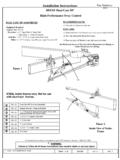
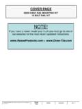
3 C Form: F205 Rev A 5-6-05 Figure 2 Trailer Forward Typical Bolting Matching Wing Sets For Wing Set Make and Model Numbers: Lippert 1621 Lippert 1621HD Check Trailer Rating (1621HD unit will require additional hole to be drilled) (Match drill hole to wing. Approximate location noted by the x ) Lippert 0719 Check Trailer rating Fabex PB-600 Series Check Trailer Rating Use The Bolt Hole Locations Noted By The A The pattern is a horizontal & a 2 vertical Note: It is recommended that you install the Goose Box one (1) position lower than the original pin box. Figure 3 Trailer Forward For Wing Set Make and Model Numbers: Lippert 1716 Lippert 1116 Check Trailer Rating Lippert 0115 Check Trailer Rating Use The Bolt Hole Locations Noted By The B The pattern is a horizontal & a vertical Note: Spacer Kit 61301 Is Needed For These Model Wings Please Refer To The Instructions In Kit 61301 For Installation Of The Spacer Kit.
4 Hardware Kit Contains: (8) 5/8-11x2 Bolts (8) 5/8-11 Nuts / (8) 5/8 HD Flat Washers (8) 5/8 Conical Lock Washers Bolts & Flat Washers Are Installed From The Outside, Conical Lock Washers and Nuts On the Inside. Torque All To 210 ft. lbs. 5/8-11 Grd. 8 Nut 5/8 Conical Washer 5/8-11x2 Bolt 5/8 Flat Washer Note: The Figure Shows a Typical Installation The Wing Is Moved Away To Better Show The Hardware Installation . Figure 4 Typical Flat Washer, Install On Outside Of Wing. Typical Conical Washer, Note Crowned Shape & Teeth. Install On Inside Of Pin Box With Teeth Against Inside Of Pin Box. Nut Side 5/8 Flat Washer 5/8 Conical Washer Note: It is recommended that you install the Goose Box one (1) position lower than the original pin box. x 1621HD Additional Hole 2009 Cequent Performance Products, Inc Sheet 3 of 7 94621IN 3/6/2012 Rev.
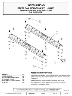
5 C Form: F205 Rev A 5-6-05 WARNING: Failure to check and follow tow ratings could result in tow vehicle damage or truck and trailer separation while towing. Trailer and its contents together must not exceed truck, hitch and/or trailer tow ratings. Towing vehicle must have a manufacturer s rated towing capacity equal to or greater than the gross trailer weight (dry weight of the trailer plus payload of the trailer). (See Fig. 5) Gross weight of trailer must not exceed 16,000 pounds for this product. Goose Ball vertical weight must not exceed 3,200 pounds (See Fig. 6). If in doubt have Goose Ball weight measured by qualified facility. GUIDELINES FOR MATCHING TOW VEHICLE AND TRAILER 1. Check Tow Ratings: Vehicle Tow Rating: _____. Goose Box Rating:_____.
6 *Gross Trailer Weight (Figure 5):_____. FACTORY TRAILER + FULL WATER TANKS + CARGO, ETC. = GROSS TRAILER WEIGHT 16,000 lbs. *Trailer weight should be the lowest of these recorded ratings for safe towing conditions. Figure 5 Figure 6 2. The Goose Box is designed for a maximum of 20% Gross Trailer Weight on the Ball (Goose Ball Vertical Weight). See Fig. 6 20% MAX. GROSS TRAILER WEIGHT (BALL WEIGHT) 80% GROSS TRAILER WEIGHT Figure 7 3. The Height of the Goose Box should be adjusted in the wing set so there is a minimum 7 in. clearance between the top of the bed and the underside of the front of the trailer for pitch and yaw of the trailer (See Figure 7). This should be checked with the Goose Box air bag inflated to 40psi. It is recommended that the Goose Box be mount in the wing set one position lower than the original Pin Box.
7 For off-road use allow more clearance between pickup walls and trailer. WARNING: Avoid putting any part of your body under the trailer or between the truck and trailer. Unexpected or accidental movement of the truck or the trailer can cause serious injury or death If you must place any part of your body under the trailer or between the truck and trailer you MUST perform ALL of the following steps: Check that the truck transmission is in park Check that the emergency brake is set Block in front of and behind all trailer tires Check that the trailer landing gear are resting on firm ground Installation / Owners Manual Goose Box A MINIMUM OF 7 IN. W/Air removing the original pin box, take note of height of the original pin box, use this as a starting reference point for the height of installing the Goose Box into the mounting wing set.
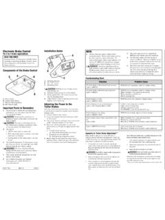
8 (See Figure 8) The Goose Box comes with all new hardware to be used. There is enough hardware for four bolts per side. Refer back to Figure 4 for bolt, washer, and nut Installation . 2009 Cequent Performance Products, Inc Sheet 4 of 7 94621IN 3/6/2012 Rev. C Form: F205 Rev A 5-6-05 ASSEMBLY INSTRUCTIONS Figure 8 Mounting Wing Set 2. Remove the existing pin box, taking care to remove any necessary wiring and/or break away switch if attached to the pin box. (If removed, the break away switch and wiring must be reinstalled after Installation is complete. The break away switch can be mounted on the side of the Goose box or side of wing, but Do NOT drill or screw on the side of the Goose Box forward of the air fill bracket.) 3. Install the Goose Box inside the mounting wings (Figure 9), Cequent Performance Products recommends using the hardware kit included with the Goose Box.
9 (4 bolts per side, 2 front row & 2 rear row) It is all grade 8 hardware. Install at least the hardware included as a minimum. Torque all bolts to 210 ft. lbs. Note: Installing the front top bolt of the Goose Box first may ease alignment. WARNING: The Goose Box is heavy, take care to maintain adequate support under the Goose Box arm until at least 2 bolts per side are installed. Failure to do so may result in death or serious injury. Figure 9 Installation / Owners Manual Goose Box HOOKING & UNHOOKING INSTRUCTIONS When hitching and unhitching the trailer to the towing vehicle, you must do all of the following: all trailer tires, in the front and behind. sure that the trailer landing gear (trailer jacks) are resting on firm ground. sure the truck is stationary, in park, with the emergency brake on.
10 Note: It is recommended that you install the Goose Box one (1) position lower than the original pin box. 2009 Cequent Performance Products, Inc Sheet 5 of 7 94621IN 3/6/2012 Rev. C Form: F205 Rev A 5-6-05 Installation / Owners Manual Goose Box WARNING: Unstable or improperly hitched trailers can fall or separate and cause serious injury or death: Never attempt to hitch trailer without first reading and following all instructions in the Manual provided with this product. Do not use without reading and understanding the Manual . Never tow a trailer that exceeds rated capacity. Towing a trailer that exceeds rated capacity can result in trailer separation, serious injury, or death. Never allow any part of the body to be placed under the trailer or between the truck and trailer.