Transcription of Installation manual - SMA RS485 MODULE
1 Installation manualSMA RS485 ( )MD485-40-IA-en-10 | Version ProvisionsThe information contained in these documents is property of SMA Solar Technology AG. Anypublication, whether in whole or in part, requires prior written approval by SMA Solar TechnologyAG. Internal reproduction used solely for the purpose of product evaluation or other proper use isallowed and does not require prior WarrantyYou can download the current warranty conditions from the Internet at trademarks are recognized, even if not explicitly identified as such. Missing designations do notmean that a product or brand is not a registered is a registered trademark of Schneider Electric and is licensed by theModbus Organization, Code is a registered trademark of DENSO WAVE and Pozidriv are registered trademarks of Phillips Screw is a registered trademark of Acument Global Technologies, Solar Technology AGSonnenallee 134266 NiestetalGermanyTel.
2 +49 561 9522-0 Fax +49 561 : 9/18/2017 Copyright 2017 SMA Solar Technology AG. All rights ProvisionsSMA Solar Technology AGInstallation manualMD485-40-IA-en-102 Table of Contents1 Information on this of RS485 the the Connection the the the the Product for of the Declaration of of ContentsSMA Solar Technology AGInstallation manual3MD485-40-IA-en-101 Information on this document is valid for the SMA RS485 MODULE ( ) with assembly designation" " from hardware version GroupThe tasks described in this document must only be performed by qualified persons. Qualifiedpersons must have the following skills: Knowledge of how an inverter works and is operated Training in how to deal with the dangers and risks associated with installing and usingelectrical devices and installations Training in the Installation and commissioning of electrical devices and installations Knowledge of the applicable standards and directives Knowledge of and compliance with this document and all safety InformationLinks to additional information can be found at.
3 Document titleDocument type" RS485 Cabling Plan" Installation a hazardous situation which, if notavoided, will result in death or serious injuryIndicates a hazardous situation which, if notavoided, can result in death or serious injuryIndicates a hazardous situation which, if notavoided, can result in minor or moderate injuryIndicates a situation which, if not avoided, canresult in property damageInformation that is important for a specific topicor goal, but is not safety-relevantIndicates a requirement for meeting a specificgoalDesired resultA problem that might occur1 Information on this DocumentSMA Solar Technology AGInstallation Display texts Elements on a user interface Terminals Elements to be selected Elements to be entered The value can be found inthe field Energy.
4 Select Settings. Enter 10 in the fieldMinutes.> Connects several elements to beselected Select Settings > Date.[Button][Key] Button or key to be selected orpressed Select [Next]. designationDesignation in this documentPV systemPV system1 Information on this DocumentSMA Solar Technology AGInstallation UseThe SMA RS485 MODULE enables SMA inverters to establish wired RS485 RS485 MODULE must only be installed in the following SMA inverters: STP 50-40 (Sunny Tripower CORE1)The inverter still complies with the standard after the product has been product must only be used in countries for which it is approved or released by SMA SolarTechnology AG and the grid components must remain within their permitted operating ranges and their installationrequirements at all this product only in accordance with the information provided in the enclosed documentationand with the locally applicable standards and directives.
5 Any other application may causepersonal injury or property to the product, changes or modifications, are only permitted with the express writtenpermission of SMA Solar Technology AG. Unauthorized alterations will void guarantee andwarranty claims and in most cases terminate the operating license. SMA Solar Technology AGshall not be held liable for any damage caused by such use of the product other than that described in the Intended Use section does not qualify as theintended enclosed documentation is an integral part of this product. Keep the documentation in aconvenient place for future reference and observe all instructions contained type label must remain permanently attached to the InformationThis section contains safety information that must be observed at all times when working on or withthe prevent personal injury and property damage and to ensure long-term operation of the product,read this section carefully and observe all safety information at all to life due to high voltages of the PV arrayWhen exposed to light, the PV array generates dangerous DC voltage, which is present in the DCconductors and the live components of the inverter.
6 Touching the DC conductors or the livecomponents can lead to lethal electric shocks. Prior to performing any work on the inverter, always disconnect the inverter from voltagesources on the AC and DC sides as described in the inverter manual . When doing so, notethat even if the DC load-break is switched off, there will be dangerous direct voltage presentin the DC conductors of the SafetySMA Solar Technology AGInstallation manualMD485-40-IA-en-106 Damage to seals on the enclosure lids in subfreezing conditionsIf you open the enclosure lids when temperatures are below freezing, the enclosure seals can bedamaged. This can lead to moisture entering the inverter. Only open the enclosure lids if the ambient temperature is not below -5 C If a layer of ice has formed on the seal of the lid when temperatures are below freezing,remove it prior to opening the enclosure lids ( by melting the ice with warm air).
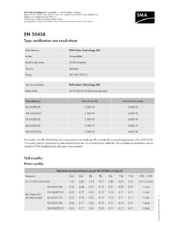
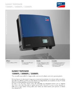
7 Observethe applicable safety to the inverter or product due to electrostatic dischargeTouching electronic components can cause damage to or destroy the inverter or the productthrough electrostatic discharge. Ground yourself before touching any SafetySMA Solar Technology AGInstallation manual7MD485-40-IA-en-103 Scope of DeliveryCheck the scope of delivery for completeness and any externally visible damage. Contact yourdistributor if the scope of delivery is incomplete or 1: Components included in the scope of deliveryPositionQuantityDesignationA1 ModuleB1 Fastening screw (M5, TX 25)C24-pole terminal blockD1 TerminatorE2 Copper foilF1 Quick Reference Guide3 Scope of DeliverySMA Solar Technology AGInstallation manualMD485-40-IA-en-1084 Product RS485 ModuleThe SMA RS485 MODULE enables SMA inverters to establish wired RS485 of the ModuleFADDCBBEF igure 2.
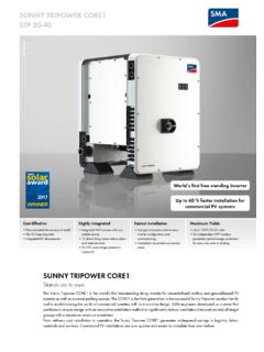
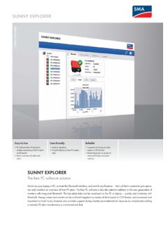
8 Design of the modulePositionExplanationAOpening for the fastening screwBOpenings for the guide pins of the communication assemblyCJacks for connecting the 4-pole terminal blocksDShield clampsEType labelFConnector strip on the back of the MODULE for connection to thecommunication assembly in the LabelThe type label clearly identifies the product. The type label is located on the front of the 3: Design of the type labelPositionExplanationADevice typeBSerial numberCHardware version4 Product DescriptionSMA Solar Technology AGInstallation manual9MD485-40-IA-en-10 You will require the information on the type label to use the product safely and when seekingcustomer support from Service (see Section 9 "Contact", page 19).
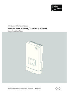
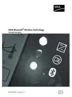
9 4 Product DescriptionSMA Solar Technology AGInstallation positionDISPLAYBATMax. 30V DCUSBFCC ID: SVF-KPIC: 9440A-KP20 MFRABX1X2 ABCF igure 4: Communication assembly in the inverter with mounting position for the modulePositionDesignationACommunication assemblyBModule slot M1*CModule slot M2*Production resources SMA Solar Technology AG recommends using MODULE slot M1 for the the ModuleMaximum number of modules per inverterYou can only use a maximum of one MODULE of the same device type per to life due to high voltages of the PV arrayWhen exposed to sunlight, the PV array generates dangerous DC voltage, which is present inthe DC conductors and the live components of the inverter. Touching the DC conductors or thelive components can lead to lethal electric shocks.
10 Prior to performing any work on the inverter, always disconnect the inverter from voltagesources on the AC and DC sides as described in the inverter manual . When doing so,note that even if the DC load-break is switched off, there will be dangerous direct voltagepresent in the DC conductors of the the enclosure lid of the DC Connection Unit. Unscrew all screws with a Torxscrewdriver (TX 25) and remove the enclosure lid carefully the screws and the enclosure lid aside and store MountingSMA Solar Technology AGInstallation the MODULE at the desired mounting location. Perform the following steps: Guide the three guide pins on thecommunication assembly through the holesin the MODULE .