Transcription of INSTALLATION REMOTE ENGINE START SYSTEM …
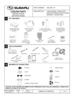
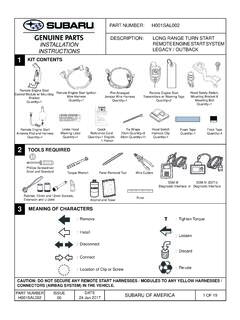
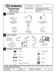
1 1 OF 17 PART NUMBERH001 SAL003 ISSUE00 DATE23 Mar 2018 SUBARU OF AMERICAPART NUMBER: H001 SAL003 DESCRIPTION: LONG RANGE TURN START REMOTE ENGINE START SYSTEM LEGACY / OUTBACKINSTALLATIONINSTRUCTIONS123 KIT CONTENTSTOOLS REQUIRED MEANING OF CHARACTERSCAUTION: DO NOT SECURE ANY REMOTE START HARNESSES / MODULES TO ANY YELLOW HARNESSES / CONNECTORS (AIRBAG SYSTEM ) IN THE Screwdriver Short and StandardWire CuttersPanel Removal ToolAlcohol and Towel: Remove : Tighten Torque: Install : Disconnect: Connect: Location of Clip or Screw: Loosen: Discard: Re-useRatchet, 10mm and 12mm Sockets, Extension and U-JointWARNING: / AVERTISSEMENTThis vehicle is equipped with a REMOTE controlled ENGINE starter. To reduce the risk of serious Injury or Death, disconnect the vehicle battery before performing any service on the v hicule est dot d'un d marreur distance.
2 Pour r duire les risques de blessures graves ou mortelles, d brancher la batterie du 4320375 REMOTE ENGINE START Control Module w/ Mounting BracketQuantity=1 REMOTE ENGINE START IgnitionWire HarnessQuantity=1 Pre-ArrangedJumper Wire HarnessQuantity=1 REMOTE ENGINE StartTransmitters w/ Warning TagsQuantity=2 REMOTE ENGINE START Antenna Pod and HarnessQuantity=1 Under Hood Warning LabelQuantity=1 Tie Wraps20cm Quantity=839cm Quantity=11 REMOTE START QUICK REFERENCE* REMOTE START Activation Press two (2) times within three (3) START ActivationPress two (2) times within two (2) seconds, then Press and Hold for three (3) RANGE ACTIVATION - ALL MODELSALTERNATE SHORT RANGE ACTIVATION - PUSH BUTTON START MODELSR emote START ShutdownPress and Hold for two (2) START ShutdownPress and Hold for three (3) : All vehicle doors, hood, trunk or rear gate must be closed (and locked on push button START models)prior to activating the REMOTE ENGINE START SYSTEM .
3 Any open entry point will prevent starting or cause the SYSTEM to shut successful activation, the REMOTE START fob will fl ash and beep one (1) time**, the horn will honk one (1) time and the side marker lights, tail lights and parking lights will fl ash one (1) time. The SYSTEM will check certain safety preconditions before starting and if all conditions are met, the ENGINE will START within fi ve (5) seconds. After the ENGINE starts, the REMOTE START fob will fl ash and beep two (2) times**, the horn will honk one (1) time and the side marker lights, tail lights and parking lights will fl ash one (1) time. While the ENGINE is running via the REMOTE ENGINE START SYSTEM , the REMOTE START fob will continue to fl ash one (1) time every three (3) seconds, the side marker lights, tail lights and parking lights will remain illuminated and the power window switches will be disabled. The ENGINE will continue to run for fi fteen (15) minutes (or current selected run time) unless one of the safety parameters below is triggered.
4 The SYSTEM also has a timer that will allow the SYSTEM to operate for a maximum of twenty (20) minutes (under multiple REMOTE START activations). Using the factory ignition key (turn START models) or Access key (push button START models) to turn on the ignition resets the twenty (20) minute the ENGINE turns over but does not START (or starts and stalls) the REMOTE ENGINE START SYSTEM will power off and then attempt to START the ENGINE three (3) additional times. The SYSTEM will not attempt to restart the ENGINE if it determines a vehicle malfunction is preventing it from starting. If the ENGINE does not START after the three (3) additional attempts, the REMOTE ENGINE START request will be START Safety ParametersFor safety and security reasons, the SYSTEM will fail to START or shut down the ENGINE during REMOTE START operation if any of the following occur: The REMOTE ENGINE START SYSTEM has operated for twenty (20) minutes between ignition ON cyclesThe horn will honk three (3) times and the parking lights will fl ash three (3) times Any of the vehicle s doors, trunk or rear gate are openThe horn will honk six (6) times and the parking lights will fl ash six (6) times The vehicle s hood is openThe horn will honk two (2) times and the parking lights will fl ash two (2) times The ignition key is resting in the ignition cylinder (turn START models)The horn will honk two (2) times and the parking lights will fl ash two (2) times The transmission shifter is not in the park positionThe horn will honk two (2) times and the parking lights will fl ash two (2) times The vehicle s brake pedal is pressed before the ignition is turned ON The horn will honk two (2) times and the parking lights will fl ash two (2)
5 Times The vehicle s ENGINE idle speed has reached a level over 3,500 RPM (this will cause the vehicle to shut down) The vehicle s security SYSTEM is triggered by opening the door, trunk or rear gate (if the security SYSTEM is armed at the time of REMOTE START activation)In addition to the items above, if the vehicle s ENGINE management SYSTEM determines there is a safety risk due to a vehicle related problem, the ENGINE will shut : TO AVOID DANGER OF CARBON MONOXIDE, NEVER REMOTE START A VEHICLE IN A CLOSED SPACE SUCH AS A CLOSED : Laws in some communities require that the vehicle be within view of anyone using the REMOTE ENGINE START SYSTEM . In some areas, use of the REMOTE ENGINE START SYSTEM may violate state, provincial or local laws. Before using the REMOTE ENGINE START SYSTEM , check your state, provincial and local laws.* See the vehicle owner s manual for more details.** Provided the REMOTE START fob is within the operating range of the SYSTEM (up to 400 with long range fob).
6 P/N: 4280881, Rev -4280881 Subar u Q ui ck R ef C ar d_19 O utback_E N G _R ev - .i ndd 14280881 Subaru Quick Ref Card_19 Outback_ENG_Rev 13/20/2018 3:49:44 P M3/20/2018 3:49:44 PMQuickReference CardQuantity=1 English, 1 FrenchTorque WrenchRulerTFlock TapeQuantity=4 BASSM IV (DST-i) Diagnostic Interface2 OF 17 PART NUMBERH001 SAL003 ISSUE00 DATE23 Mar 2018 SUBARU OF AMERICA1. Using a 12mm socket/ratchet, disconnect the negative battery terminal. (FIGURE A) NOTE: Do not disconnect the battery cable from the battery Starting at the bottom, use a panel removal tool to carefully remove the left side dashboard panel. (FIGURE B) Remove one (1) Phillips screw securing the lower dashboard panel on the left side of the dashboard. (FIGURE C)3. Remove the driver s side under dashboard fi nisher panel by depressing the three (3) pressure clips and pulling downward. Unplug all connectors attached to the dashboard fi nsher panel.
7 (FIGURE D) 4 VEHICLE PREPARATIONFIGURE AFIGURE BFIGURE CFIGURE D3 OF 17 PART NUMBERH001 SAL003 ISSUE00 DATE23 Mar 2018 SUBARU OF AMERICA4. Using a panel removal tool, carefully remove the driver s left side lower dashboard panel by pulling straight out. Unplug all connectors attached to the dashboard panel. (FIGURE E) 4 VEHICLE PREPARATIONFIGURE E6. Remove the steering column shroud. Using a Phillips screwdriver, remove one (1) Phillips screw on the left side face and one (1) Phillips screw on the right side face of the steering column shroud. Carefully unsnap and remove the lower steering column shroud panel and then remove the upper steering column shroud panel. (FIGURE G)NOTE: Rotate the steering wheel toaccess the Phillips screws on the face ofthe steering column. FIGURE GLeft SideRight SideFIGURE F5. Using a 10mm socket/ratchet, remove the two (2) 10mm bolts securing the metal knee bolster.
8 (FIGURE F)4 OF 17 PART NUMBERH001 SAL003 ISSUE00 DATE23 Mar 2018 SUBARU OF AMERICAFIGURE KFIGURE JClean mounting area with alcohol5 WINDSHIELD MOUNT ANTENNA INSTALLATION - NON EYESIGHT EQUIPPED VEHICLESA-PILLAR PANEL REMOVAL1. Remove the driver s side A-pillar panel by releasing the two (2) body clips along with the lower clips where the A-pillar panel meets the dashboard. (FIGURE H)2. Rotate the A-pillar panel away from the dashboard and release the airbag tether clip from the top of the A-pillar panel. (FIGURE I) CAUTION! Use care when performing this step toavoid damage to the curtain airbag. If the airbag isdamaged, it must be Inspect the white protective (non-woven fabric) of the curtain airbag. If the fabric is damaged, the curtain airbag assembly must be HFIGURE IIMPORTANT! THIS SECTION ONLY APPLIES TO VEHICLES WITHOUT THE EYESIGHT SYSTEM . FOR VEHICLES EQUIPPED WITH THE EYESIGHT SYSTEM , DISREGARD THIS SECTION AND PROCEED TO SECTION POD MOUNTING / HARNESS ROUTING1.
9 Plug the 5-pin connector from the antenna harness into the 5-pin port on the antenna pod. (FIGURE J)2. Using alcohol, clean the glass surface near the antenna mounting area. Remove the adhesive backing on the antenna pod and apply the antenna to the windshield. The base of the antenna pod (harness connection end) should line up to the area of the windshield where the solid black fi lm and dotted black fi lm meet and 25mm (1 ) left of the windshield center mark. (FIGURE K) 5 OF 17 PART NUMBERH001 SAL003 ISSUE00 DATE23 Mar 2018 SUBARU OF AMERICA5 WINDSHIELD MOUNT ANTENNA INSTALLATION - NON EYESIGHT EQUIPPED VEHICLES, continued3. Route the antenna harness across the headliner and down the A-pillar. Tuck the cable below the driver s side dashboard through the opening closest to the windshield and allow the harness to hang loose behind the vehicle s dashboard mounted fusebox. (FIGURE L) The antenna harness will be plugged into the REMOTE ENGINE START control module during Section Secure the antenna harness to the vehicle wire harness in the A-pillar in fi ve (5) places using the supplied 20cm tie wraps.
10 (FIGURE M)5. Using one of the supplied 20cm tie wraps, secure the antenna harness to the vehicle wiring behind the Re-install the airbag tether clip to the A-pillar panel and rotate the panel into Re-install the A-pillar TO SECTION 7 FIGURE LFIGURE M6 OF 17 PART NUMBERH001 SAL003 ISSUE00 DATE23 Mar 2018 SUBARU OF AMERICA10mm20mmFIGURE N6 WINDSHIELD MOUNT ANTENNA INSTALLATION - EYESIGHT EQUIPPED VEHICLESANTENNA MOUNTING1. Mount the antenna pod to the top left hand side of the windshield, near the headliner and driver s side A-pillar trim panel with the antenna pod finger facing the passenger s side. Using alcohol, clean the area thoroughly. (FIGURE N)2. Using a ruler, ensure the top left corner of the antenna pod will be 20mm (3/4 ) from the right corner of the A-pillar trim panel in a straight line and 10mm (3/8 ) down from the headliner to the upper right corner of the antenna pod.