Transcription of INSTALLATION REMOTE ENGINE START SYSTEM FORESTER …
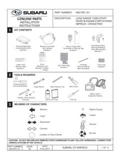
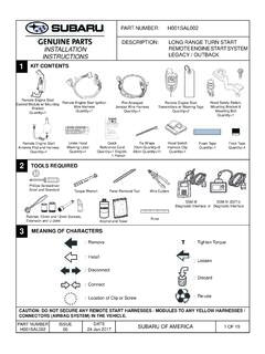
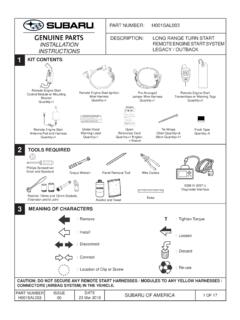
1 PART NUMBER: H001 SSJ100. DESCRIPTION: LONG RANGE KEY START . REMOTE ENGINE START SYSTEM . INSTALLATION . FORESTER . INSTRUCTIONS. 1 KIT CONTENTS. REMOTE ENGINE START REMOTE ENGINE START REMOTE ENGINE START Control Module (ECU) Wire Harness Transmitters w/ Warning Tags Quantity=1 Quantity=1 Quantity=2. REMOTE START QUICK REFERENCE*. LONG RANGE ACTIVATION - ALL MODELS ALTERNATE ACTIVATION - PUSH BUTTON START MODELS. REMOTE START Activation REMOTE START Activation Press Two (2) Times Press Two (2) Times Within (2) Seconds, Then Within Three (3) Seconds Press and Hold For Three (3). REMOTE START Shutdown Seconds Press and Hold For REMOTE START Shutdown Three (3) Seconds Press and Hold For Two (2) Seconds NOTE: All vehicle doors, hood, trunk or rear gate must be closed prior to activating the REMOTE ENGINE START SYSTEM . Any open entry point will prevent starting or cause the SYSTEM to shut down.
2 Upon successful activation, the REMOTE START fob will flash and beep one (1) time**, the horn will honk one (1) time and the side marker lights, tail lights and parking lights will flash one (1) time. The SYSTEM will check certain safety preconditions before starting and if all conditions are met, the ENGINE will START within five (5) seconds. After the ENGINE starts, the REMOTE START fob will flash and beep two (2) times**, the horn will honk one (1) time and the side marker lights, tail lights and parking lights will flash one (1) time. While the ENGINE is running via the REMOTE ENGINE START SYSTEM , the REMOTE START fob will continue to flash one (1) time every three (3) seconds, the side marker lights, tail lights and parking lights will remain illuminated and the power window switches will be disabled. The ENGINE will continue to run for fifteen (15) minutes unless one of the safety parameters below is triggered.
3 The SYSTEM also has a timer that will allow the SYSTEM to operate for a maximum of twenty (20) minutes (under multiple REMOTE START activations). Using the factory ignition key (Turn START models) or Access key (Push button START models) to turn on the ignition resets the twenty (20) minute timer. If the ENGINE turns over but does not START (or starts and stalls) the REMOTE ENGINE START SYSTEM will power off and then attempt to START the ENGINE three (3) additional times. The SYSTEM will not attempt to restart the ENGINE if it determines a vehicle malfunction is preventing it from starting. If the ENGINE does not START after the three (3) additional attempts, the REMOTE ENGINE START request will be aborted. WARNING: / AVERTISSEMENT REMOTE START Safety Parameters For safety and security reasons, the SYSTEM will fail to START or shut down the ENGINE during REMOTE START operation if any of the following occur: This vehicle is equipped with a REMOTE controlled ENGINE starter.
4 The REMOTE START SYSTEM has operated for twenty (20) minutes between ignition ON cycles The horn will honk three (3) times and the parking lights will flash three (3) times To reduce the risk of serious Injury or death, switch ENGINE starter Any of the vehicle's doors, trunk or rear gate are open The horn will honk six (6) times and the parking lights will flash six (6) times The vehicle's hood is open SYSTEM into service mode and disconnect the vehicle battery . The horn will honk two (2) times and the parking lights will flash two (2) times The ignition key is resting in the ignition cylinder (Turn START models). before performing any service on the vehicle.. The horn will honk two (2) times and the parking lights will flash two (2) times The transmission shifter is not in the park position The horn will honk two (2) times and the parking lights will flash two (2) times The vehicle's brake pedal is pressed before the vehicle ignition is turned ON.
5 Ce v hicule est dot d'un d marreur distance. Pour r duire les . The horn will honk two (2) times and the parking lights will flash two (2) times The vehicle's ENGINE idle speed has reached a level over 3,500 RPM (this will cause the vehicle to shut down). risques de blessures graves ou mortelles, mettre le d marreur The vehicle's security SYSTEM is triggered by opening the door, trunk or rear gate (if the security SYSTEM is armed at the time of REMOTE START activation). distance en mode service et d brancher la batterie du v hicule In addition to the items above, if the vehicle's ENGINE management SYSTEM determines there is a safety risk due to a vehicle related problem, the ENGINE will shut down. avant d'effectuer des travaux d'entretien sur celui-ci. WARNING: TO AVOID DANGER OF CARBON MONOXIDE, NEVER REMOTE START A VEHICLE IN A CLOSED.
6 SPACE SUCH AS A CLOSED GARAGE. NOTE: Laws in some communities require that the vehicle be within view of anyone using the REMOTE ENGINE START . In some areas, use of the REMOTE ENGINE START may violate state, provincial or local laws. Before using the REMOTE ENGINE START , check your state, provincial and local laws. * See the vehicle owner's manual for more details. ** Provided that the REMOTE START fob is within the operating range of the SYSTEM . P/N: 4280648, Rev - Under Hood Quick Tie Wraps Warning Label Reference Card 39cm Quantity=6. Quantity=1 Quantity=1 English, 1 French 2 TOOLS REQUIRED. Phillips Screwdriver Short and Standard Torque Wrench Panel Removal Tool Wire Cutters B A. SSM IV (DST-i). Diagnostic Interface Ratchet, 10mm Socket &. Extension Alcohol and Towel Pick Tool 3 MEANING OF CHARACTERS. : Remove T : Tighten Torque : Loosen : Install : Disconnect : Discard : Connect : Re-use : Location of Clip or Screw CAUTION: DO NOT SECURE ANY REMOTE START HARNESSES TO ANY YELLOW HARNESSES / CONNECTORS.
7 (AIRBAG SYSTEM ) IN THE VEHICLE. PART NUMBER ISSUE DATE. H001 SSJ100 - 9 May 2018. SUBARU OF AMERICA 1 OF 9. 4 VEHICLE PREPARATION. 1. Using a 10mm socket/ratchet, disconnect the negative battery terminal. (FIGURE A). NOTE: Do not disconnect the battery cable from the battery post. NOTE: DO NOT PROCEED TO THE NEXT STEP FOR ONE (1). MINUTE TO ALLOW TIME FOR THE AIRBAG POWER SUPPLY. TO DISCHARGE. con exp DANG. Cigaret ER. nec lode Do not . Alw tes, flam EXPL. es, or OSIVE. chargeays shie sparks ld cou GASE. KEE tions withor use booeyes and ld cause S. P. PO VENT CA out properster cables face bat from tery to Con ISON PS TIG inst or adjubattery s sulf CAUS. tain HT ruct st . eyes ion wat or clothing uric acid ES SE AND LEV and traipos t . Inev . Avoid VER. er or EL ning . KEEP call a phy ent con BURN. of acc tact OUT sician imm iden with skinS.
8 OF RE ediatelyt flush with , AC H OF . CHILD SO. REN LD. SUBA BY. SUBA RU OF. CH RU AM. ERRY PLAZ ERIC. HILL A A. , NJ . BO. 0803 X 60. 4-60 00. 00. FIGURE A. 2. Using a panel removal tool, carefully remove the left side dashboard panel by starting at the bottom access notch and working upward to disengage four (4) pressure clips. (FIGURE B). 3. Using a Phillips screwdriver, remove two (2) Phillips screws securing the driver's side lower dashboard panel. (FIGURE C & D). 4. Using a panel removal tool, carefully remove the driver's side lower dashboard panel by pulling straight out to disengage thirteen (13) pressure clips. Unplug all connectors attached to the dashboard panel. (FIGURE D). FIGURE B. +. FIGURE C FIGURE D. PART NUMBER ISSUE DATE. H001 SSJ100 - SUBARU OF AMERICA 2 OF 9. 9 May 2018. 4 VEHICLE PREPARATION, continued 5.
9 Using a 10mm socket/ratchet/extension, remove the two (2) 10mm nuts securing the driver's side lower airbag/. knee bolster. (FIGURE E). FIGURE E. 6. Remove the lower airbag/knee bolster. Using a pick tool, disengage the yellow connector lock by lifting upward. (FIGURE F). Using a panel removal tool, carefully lift upward to unplug the electrical connector and place the airbag/. knee bolster panel in a safe area. FIGURE F. PART NUMBER ISSUE DATE. H001 SSJ100 - 9 May 2018. SUBARU OF AMERICA 3 OF 9. 5 REMOTE ENGINE START ECU MOUNTING. 1. Locate the DC-DC Converter Module mounted to the vehicle's dashwall to the left of the brake pedal assembly. (FIGURE G). Clean with Alcohol 2. Using alcohol, clean the DC-DC Converter Module bracket. (FIGURE G). NOTE: Ensure the DC-DC Converter Module Bracket is completely dry. DC-DC Converter Module FIGURE G.
10 3. Remove the one (1) release liner from the REMOTE ENGINE START ECU and attach it to the module bracket, as shown. Press firmly in place for at least thirty (30) seconds. (FIGURE H). 4. Using one (1) of the supplied 39cm tie wraps, secure the REMOTE ENGINE START ECU to the DC-DC Converter Module. Trim off the excess tie wrap. (FIGURE H). DC-DC Converter Module FIGURE H. PART NUMBER ISSUE DATE. H001 SSJ100 - SUBARU OF AMERICA 4 OF 9. 9 May 2018. 6 REMOTE ENGINE START WIRE HARNESS CONNECTIONS / ROUTING. 1. Locate and release the vehicle's 6-pin pre-fit ignition connector secured to the vehicle's wire harness with breakaway tape near the base of the steering column. (FIGURE I). Steering FIGURE I Column 2. Locate and release the vehicle's 4-pin and 2-pin pre-fit connectors secured to the vehicle's wire harness with breakaway tape near the upper driver's side kick panel area.