Transcription of Installing and Testing a GFCI Receptacle
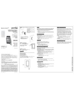
1 Installing and Testing a GFCI ReceptaclePlease read this leaflet completely before getting ! To prevent severe shock or electrocution always turn the power OFF at the service panel before working with wiring. Use this GFCI with copper or copper-clad wire. Do not use it with aluminum wire. Do not install this GFCI Receptacle on a circuit that powers life support equipment because if the GFCI trips it will shut down the equipment. For installation in wet locations, protect the GFCI Receptacle with a weatherproof cover that will keep both the Receptacle and any plugs dry. Must be installed in accordance with national and local electrical The GFCI's featuresGreen/RedStatusIndicatorLED1. What is a GFCI?A GFCI Receptacle is different from conventional receptacles. In the event of a ground fault, a GFCI will trip and quickly stop the flow of electricity to prevent serious of a ground fault:Instead of following its normal safe path, electricity passes through a person's body to reach the ground.
2 For example, a defective appliance can cause a ground GFCI Receptacle does NOT protect against circuit overloads, short circuits, or shocks. For example, you can still be shocked if you touch bare wires while standing on a non-conducting surface, such as a wood :GFCI's contain a lockout feature that will prevent RESET if: There is no power being supplied to the GFCI. The GFCI is miswired due to reversal of the LINE and LOAD leads. The GFCI cannot pass its internal test, indicating that it may not be able to provide protection in the event of a ground Should you install it? Installing a GFCI Receptacle can be more complicated than Installing a conventional sure that you: Understand basic wiring principles and techniques Can interpret wiring diagrams Have circuit wiring experience Are prepared to take a few minutes to test your work, making sure that you have wired the GFCI Receptacle correctly4.
3 LINE vs. LOADA cable consists of 2 or 3 wires. Cable WiresLINE cable:Delivers power from the service panel (breaker panel or fuse box) to the GFCI. If there is only one cable entering the electrical box, it is the LINE cable. This cable should be connected to the GFCI's LINE terminals cable:Delivers power from the GFCI to another Receptacle in the circuit. This cable should be connected to the GFCI's LOAD terminals only. The LOAD terminals are under the yellow sticker. DO NOT remove the sticker at this Turn the power OFFPlug an electrical device, such as a lamp or radio, into the Receptacle on which you are working. Turn the lamp or radio ON. Then, go to the service panel. Find the breaker or fuse that protects that Receptacle . Place the breaker in the OFF position or completely remove the fuse.
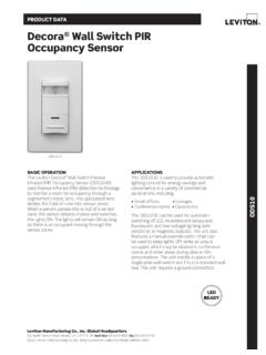
4 The lamp or radio must turn , plug in and turn ON the lamp or radio at the Receptacle 's other outlet to make sure the power is OFF at both outlets. If the power is not OFF, stop work and call an electrician to complete the Identify cables/wiresImportant:DO NOT install the GFCI Receptacle in an electrical box containing (a) more than four (4) wires (not including the grounding wires) or (b) cables with more than two (2) wires (not including the grounding wire). Contact a qualified electrician if either (a) or (b) are you are replacing an old Receptacle , pull it out of the electrical box without disconnecting the wires. If you see one cable (2-3 wires), it is the LINE cable. The Receptacle is probably in position C (see diagram to the right). Remove the Receptacle and go to step 7A.
5 If you see two cables (4-6 wires), the Receptacle is probably in position A or B (see diagram to the right). Follow steps a-e of the procedure to the : box with two (2) cables (4-6 wires):(a) Detach one cable's white wire and hot wires from the Receptacle and cap each one separately with a wire connector. Make sure that they are from the same cable.(b) Re-install the Receptacle in the electrical box, attach faceplate, then turn the power ON at the service panel.(c) Determine if power is flowing to the Receptacle . If so, the capped wires are the LOAD wires. If not, the capped wires are the LINE wires.(d) Turn the power OFF at the service panel, label the LINE and LOAD wires, then remove the Receptacle .(e) Go to step in circuit:The GFCI's place in the circuit determines if it protects other receptacles in the circuit:Placing the GFCI in position A will also provide protection to "load side" receptacles B and C.
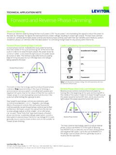
6 On the other hand, placing the GFCI in position C will not provide protection to receptacles A or B. Remember that receptacles A, B, and C can be in different MONTHLYTEST MENSUELFOLLOW INSTRUCTIONSSUIVEZ INSTRUCTIONSRESETRESETTESTTESTFRONT VIEWR eceptacleTEST button: See step 8 RESET button: See step 8 Mounting BracketSelf-Ground ClipOutletOutletBACK VIEWG rounding lead (Green): Connection for bare copper or green wireLINEHot lead: Connection for the LINE cable's Hot wireLINEW hite lead:Connection for the LINE cable's Neutral wireLOADHot lead: Connection for the LOAD cable's Hot wireLOADW hite lead:Connection for the LOAD cable's Neutral wireA yellow sticker coversthe LOAD leads. DO NOT remove the sticker at this time. 7. Connect the wires (choose A or B).. only after reading other side completelyOR A: One Cable (2 or 3 wires) entering the box B: Two cables (4 or 6 wires) entering the boxBlackWhiteWhiteBlackGreenLOADCHARGELO ADLINE/LIGNELINE/LIGNECHARGEG rounding connection to box (if box has a grounding terminal)Wire ConnectorLINE cable brings power to the GFCIE lectricalBoxAbout Wire Connections:Connect the LINE cable wires to the LINE leads: The white wire connects to the GFCI WHITE lead.
7 The black wire connects to the GFCI HOT the LOAD ( Receptacle ) cable wires to the GFCI LOAD leads: Remove the YELLOW sticker wrapping the leads. The white wire connects to the GFCI WHITE lead. The black wire connects to the GFCI HOT the grounding wires (only if there is a grounding wire): If the box has a grounding terminal, Connect a 6-inch bare copper (or GREEN) 12 or 14 AWG wire to the grounding terminal on the box. Connect the ends of the GFCI and box grounding wires to the LINE or LOAD cable's bare copper (or GREEN) wire using a wire connector. If these wires are already in place, check the the installation: Fold the wires into the box, keeping the grounding wire away from the WHITE and HOT terminals. Screw the Receptacle to the box and attach the faceplate. Go to step Wire Connections:Connect the LINE cable wires to the GFCI LINE leads: The white wire connects to the GFCI WHITE lead.
8 The black wire connects to the GFCI HOT the grounding wire (only if there is a grounding wire): For a box with no grounding terminal (diagram not shown): Connect the LINE cable's bare copper (or GREEN) wire directly to the grounding lead on the GFCI Receptacle . For a box with a grounding terminal (diagram shown above): Connect a 6-inch bare copper (or GREEN) 12 or 14 AWG wire to the grounding terminal on the box. Connect the ends of the GFCI and box grounding wires to the LINE cable's bare copper (or GREEN) wire using a wire connector. If these wires are already in place, check the the installation: Remove the YELLOW sticker wrapping the load leads and use the wire connectors provided to cap the unused load leads. Insert wire straight into wire connector and screw wire connector clockwise making sure there are no bare conductors below the wire connectors.
9 Secure each connector with electrical tape. Fold the wires into the box, keeping the grounding wire away from the WHITE and HOT leads. Screw the Receptacle to the box and attach the faceplate. Go to step cable brings power to the GFCIE lectricalBoxWire ConnectorGrounding connectionto box (if box has a grounding terminal)LOAD cable feeds power to other Receptacle (s)PK-A3085-10-00-2A 2015 Leviton Mfg. Co., Test your workWhy perform this test? If you miswired the GFCI it may not prevent personal injury or death due to a ground fault (electrical shock). If you mistakenly connect the LINE wires to the LOAD terminals, the GFCI will not reset and will not provide power to either the GFCI Receptacle face or any receptacles fed from the :(a) This GFCI is shipped from the factory in the tripped condition and cannot be reset until it is wired correctly and power is supplied to the device.
10 Plug a lamp or radio into the GFCI (and leave it plugged in). Turn the power ON at the service panel. Ensure that the GFCI is still in the tripped condition by pressing the TEST button. If the lamp or radio is OFF, and the GFCI will not reset, go to the Troubleshooting section as the Line and Load connections are reversed.(b) Press the RESET button fully and release. If the Status Indicator Light turns Green and the lamp or radio is ON, the GFCI has been installed correctly. If the Status Indicator Light turns or continuously blinks Red, or the GFCI cannot be reset, go to the Self-Test Operation section.(c) If you installed your GFCI using step 7B, plug a lamp or radio into surrounding receptacles to see which one(s), in addition to the GFCI, lose power when you press the GFCI TEST button.