Example: stock market
Instruction Manual - Danfoss
5 Electromechanical Bypass (EMB2) Operation 6-1 ... Figure 6.3: Bypass Trip Time Delay 6-10 Figure 6.4: Drive Display with Bypass Start Time Delay Active 6-11 ... ECB with Control Relays, Part 1 8-12 Figure 8.12: ECB with Control Relays, Part 2 8-13 Figure 8.13: Non-bypass 8-14
Tags:
Information
Domain:
Source:
Link to this page:
Documents from same domain
8D problem solving - files.danfoss.com
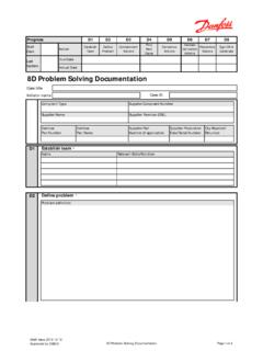
files.danfoss.comWhy was the Problem not detected in time? Approach/ Tool Applied What Recurrence Classification D4 Is data validated Due date Describe root cause / graphical representation of findings Find root cause Draft issue, 2012-12-12 Approved by: DBS-Q 8D Problem Solving Documentation Page 3 of 4. Validated (Ok/Not Ok) Who Where Who
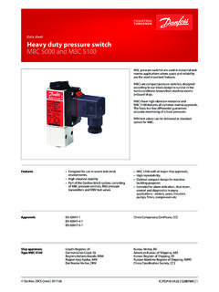
Data sheet Heavy duty pressure switch MBC 5000 …
files.danfoss.com© Danfoss | DCS (jmn) | 2017.06 MBC pressure switches are used in industrial and marine applications where space and reliability are the most important features.
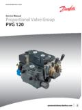
PVG 120 Proportional Valve Service Manual - Danfoss
files.danfoss.comMAKING MODERN LIVING POSSIBLE Service Manual Proportional Valve Group PVG 120 powersolutions.danfoss.com
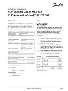
VLT® Encoder Option MCB 102 - files.danfoss.com
files.danfoss.comSet-up and Connection VLT® AutomationDrive FC 301/FC 302 with VLT® Encoder Option MCB 102 supports multiple encoder configurations which can be used as speed and/or position feedback for closed-loop flux motor control, closed-loop speed control, and closed-loop position
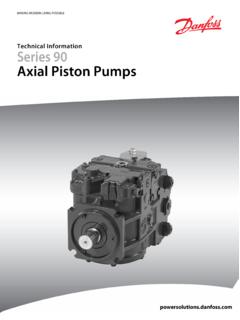
Series 90 Axial Piston Pumps Technical Information Manual
files.danfoss.comparallel axial piston/slipper concept in conjunction with a tiltable swashplate to vary the pump’s displacement. Reversing the angle of the swashplate reverses the flow of oil from the pump and thus
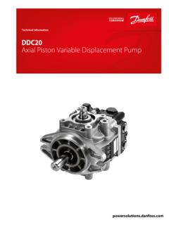
DDC20 Axial Piston Variable Displacement Pump Technical ...
files.danfoss.comThe DDC20 is a compact and lightweight variable displacement axial piston pump intended for use in closed circuit low to medium power applications. DDC20 is a direct displacement control pump utilizing an advanced slipper piston design. The flow rate is infinitely variable between zero and maximum. ... DDC20 Axial Piston Variable Displacement ...
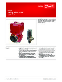
Data sheet Safety relief valve Type POV - files.danfoss.com
files.danfoss.comTechnical data Installation To ensure exact operation of the valve it should be installed with the spring housing upwards (refer to "Installation of compressor safety valve POV + BSV" on the following pages). ... Data sheet | Safety relief valve, type POV 0 × A.
VLT HVAC Drive FC 102 1.1-90 kW - files.danfoss.com
files.danfoss.com• VLT® HVAC Drive Metasys, Operating Instructions • VLT ® HVAC Drive FLN, Operating Instructions Danfoss technical literature is available in print from local
VLT AutomationDrive FC 301/302 0.25-75kW - files.danfoss.com
files.danfoss.comMAKING MODERN LIVING POSSIBLE Design Guide VLT® AutomationDrive FC 301/302 0.25-75 kW www.danfoss.com/drives
VLT® AQUA Drive FC 202 0.25-90 kW - files.danfoss.com
files.danfoss.comContents 1 Introduction 8 1.1 Purpose of the Design Guide 8 1.2 Organisation 8 1.3 Additional Resources 8 1.4 Abbreviations, Symbols and Conventions 9 1.5 Definitions
Related documents

Know About Different Types of Relays - ElProCus
www.elprocus.comTime Delay Relays 14 5. Thermal Relay 15 5.1 Bimetallic Thermal Relays 16 5.2 Solid State Thermal Relays 16 ... processes or equipment regardless of whether they are electronic or electromechanical. All the relays respond to one or more electrical quantities like voltage or current such that

Understanding Fault Technical Report
www.nrel.govthe desired tripping time (i.e., time delay for relay coordination and system reliability purposes). The decision to trip open or to close the circuit breaker is made by the relay ... • Electromechanical relays were first introduced in the early 1900s. A typical electromechanical relay is pictured in Figure 4. Electromechanical relays are either

Medium Voltage Circuit Breaker Course Chapter 3.0 Student ...
www.nrc.govelectromechanical relays can be classified into instantaneous (magnetic attraction) and time-delay (torque-controlled) units. o Instantaneous units: This type of relay unit may consist of a solenoid and plunger or a solenoid and a hinged armature. Magnetic attraction is the operating force. o Time-delay units: This type of unit consists of an ...

E1 Plus Overload Relay Specifications
literature.rockwellautomation.comWhile electromechanical overload relays pass motor current through ... time-current status of the motor thermal capacity utilization value. Thermal memory A thermal memory circuit allows the E1 Plus Overload Relay to model ... Trip delay is fixed at 50 ms ± 20 ms.

Power System Protection - Philadelphia University
www.philadelphia.edu.joTime-overcurrent relays (ANSI 51 relays) have two basic settings: the pickup current and the time delay settings. The process for determining the time delay setting involves: (1) Calculation of a time delay value in definite-time overcurrent elements (2) Selection in inverse-time overcurrent elements of a time-current curve from a family of curves.

UNIT I - INTRODUCTION OF RELAYS
www.bharathuniv.ac.inclosed contact, time delay 7 8 Normally open contact, time delay 1 2 4 Changeover contact 5 6 8 Changeover contact, time delay A1 A2 The coil terminals (common) relay contacts are either normally open (NO) or normally closed (NC), The term “normally” refers to the state in which the coil is not energized. Relays can have many independent