Transcription of Instruction Manual - heat press
1 Instruction Manual MODELS 178, 178H, 178T, 374D, 374H, 374HT, 475, 475S, 495, 495S, 674, 674S, 674M, 674A. Congratulations! You have just purchased the finest heat press of its kind available. This press is designed to handle any type of transfer and fusing operation, from plastisol and ink transfers to sublimation and heat activated embroidery. Geo. Knight & Co. has called on their 110 years (Since 1885) of experience with fusing and molding equipment, to design and manufacture the highest quality machinery on the market. Transfer press Operation Before plugging your unit into a 120v circuit, be certain that the line has a rating of a least 15 amps (Models 475, 475S, 674, 674S,M,or A) or 10 amps (Model 178, 178T, 374H, 374HT). Switch on the solid state circuit breaker and the press will begin to heat up.
2 You will notice that a red heating light will engage indicating that the thermostat is calling for heat. There is also a green at heat light that will come on when the desired temperature setting is reached. We have factory set your thermostat to 350 f (390 for sublimation transfers). When the press reaches that temperature, the green at heat light will come on. The red and green lights will alternate throughout the day as the press is used. To set the dwell time on your press simply position the automatic timer dial to the desired setting. The timer is located on the universal console and can be set anywhere from 0-60 seconds. When the heater block is brought down and locked into place, a mercury timing element activates the automatic timer and the timer begins to count down internally.
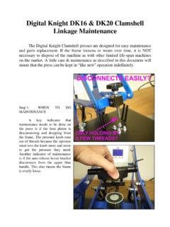
3 At the elapsed time a buzzer will sound indicating completion of the printing cycle. When the heater block is lifted back up to the fully open position, the timer is automatically reset and ready to count down again. The amount of pressure on the printing surface can be regulated by simply turning the pressure adjusting knob (screw) on top of the support arm. Turning the knob toward the "+" sign (counter-clockwise) will increase the pressure. Turning it toward the "-" sign (clockwise) will decrease the pressure. The unique linkage system designed by Geo. Knight & Co. reduces the amount of resistance felt in the handle as the press is locked into place, while at the same time providing sufficient pressure on the printing surface to ensure good transfer adhesion.
4 There is no need to feel an undo amount of resistance when the closing the press . A few experimental printings will give you the feel of what pressure gives you the best results. Pivoting oilite bushings provide a self lubricating axis at the stress points of the linkage system for maintenance-free operation. Occasional cleaning of dust and lint is a good idea. The actual printing surface is a sheet of specially formed silicone rubber. This long lasting sponge is heat resistant and with proper maintenance (keeping it clean) will provide you a smooth, level surface for many transfer applications. The holes and lag bolts at the bottom of the base frame are provided to secure your press to a work bench or table. For Models 178, 178T. Page 1. The printing surface of these cap sealers is 4" x 7", which will enable printing of virtually the entire front panel of most caps.
5 Interchangeable bottom forms are available for printing golf caps, euro-style caps, &. painter's caps (3 x 6), visors (2 x 7), and children's caps (3 x 5). The cap sealers feature a teflon transfer hold down band. This heat resistant, anti-static fabric will hold the transfer in place on the cap before the heater block presses and also during the printing process. This will keep the transfer from slipping or shifting when the press initially clamps down on the transfer and garment. As the heater is raised, the teflon hold down band will remain on the printed surface until the heater block is lifted past a 45 angle. When the cap is first placed on the bottom form, the bill of the cap should be facing upwards and toward the operator. If the cap has a sweat guard at the bottom of the panel and bill, flip the sweat guard out so that it is not resting on the bottom form.
6 This will insure an even, flat printing surface for the transfer. The back strap of the cap should be fitted underneath the half-moon clamp under the bottom table. This cap hold down device (half moon clamp/bracket). holds the cap tight against the bottom form to insure a wrinkle free pressing. To adjust the height of the cap hold down bracket, loosen the wing nut and adjust the position for the type of cap being used, so that the back strap of the cap can be fitted under the bracket tightly. The cap should have no wrinkles on the printing surface and should be held down firmly to the bottom table by the half moon bracket (cap hold down device). Pivoting Heat Platen & Bottom Tables MODEL 674A ONLY. The 674A 16 x 20 heat transfer press has the unique feature of a rotating heat platen in order to accommodate a 20 inch dimension in either a left-to-right or front-to-back direction.
7 The bottom table also is removable and rotatable. To change rotate platens: - Lower handle of machine approximately half way down to the closed position. - Lift up on spring loaded latch located on the back side of cross arm. The cross arm is the bar that the pressure adjustment screw is located on. Be sure to lift the latch completely out of the locating hole in the heater block cover. - Pivot the heater block by holding onto the universal console. - Align latch with secondary locating hole in the heater block cover. - Release latch slowly into hole. - To position the bottom table printing area, lift the handle of the press and raise heater block completely off the surface area to the up-right position. - Take hold of the sides of the table (Left-to-Right) and lift up on the right hand side.
8 The pin on the bottom of the table will lift out of the hole in the frame. - Slide table to the left and lift entire table straight up and off of the table support. The screw head on the bottom of the table will slide into the slot of the frame and lift off of the table support. - By aligning the table screw head and pins with the appropriate frame holes, the table can be positioned in relation to the heater block. Transfer press Overview Page 2. Heater Block assembly The heater block assembly is a permanent mold aluminum casting. This type of mold reduces imperfections in the casting which can cause air bubbles to form and pock marks to develop on the surface. The density of the casting coupled with a stress relieving process (600 F for 8 hours) bakes out any moisture in the casting, ensuring a warp free surface that is unaffected by transfer temperatures.
9 The surface of the casting is then ground with a state of the art carbide platen milling machine to produce a perfectly flat heating area. A. hard teflon coating seals the heater block and protects it from scratches, and also facilitates cleaning. A copper coated, steel tubular calrod (UL approved) is permanently cast within the aluminum heater block casting, to provide even heat distribution throughout the surface. This coil heat unit is controlled by a solid state thermostat which governs the heater to give you precise temperature regulation( 5 F). Heater Block Casting - Aluminum casting, platen milled and teflon coated with cast-in heat coil. Thermostat - Temperature sensing device mounted to heat platen that controls heat demand from heat coil cast within the platen.
10 Thermometer - Measures heater block temperature on the surface of the platen. Banana Pins - Male connector mounted on heater block cover to which universal console is mounted. A vital part of the machine - great care should be taken to protect these pins from being bent, loosened, or otherwise damaged Wire Harness - High temperature teflon wiring that connects heat coil to thermostat and the universal console. Pressure Block - Case hardened threaded nut, mounted on heat platen, that receives the pressure adjusting screw. Insulation - Fiberglass insert to contain heat build-up within heater block cover. Pressure Adjusting Screw - Case hardened threaded rod, that attaches entire heater block assembly to base. Lifter Springs - Steel springs to assist operator in raising heater block assembly of printing area.