Transcription of Instructions for ND, CND, HND, CHND, NDC and …
1 29C106 FFile 29-000 Effective September 1999, Supersedes 29C106E dated 1/98DO NOT ATTEMPT TO INSTALL OR PERFORM MAIN-TENANCE ON EQUIPMENT WHILE ENERGIZED. DEATH, SEVERE PERSONAL INJURY, OR SUBSTAN-TIAL PROPERTY DAMAGE CAN RESULT FROM CON-TACT WITH ENERGIZED EQUIPMENT. ALWAYS VERIFY THAT NO VOLTAGE IS PRESENT BEFORE PROCEEDING WITH THE TASK, AND ALWAYS FOL-LOW GENERALLY ACCEPTED SAFETY IS NOT LIABLE FOR THE MISAP-PLICATION OR MISINSTALLATION OF ITS PROD-UCTS. THIS PRODUCT IS A DIRECT REPLACEMENT FOR WESTINGHOUSE circuit user is cautioned to observe all recommendations, warnings, and cautions relating to the safety of personnel and equipment as well as all general and local health and safety laws, codes, and recommendations and information contained herein are based on Cutler-Hammer experience and judgement, but should not be considered to be all-inclusive or cover-ing every application or circumstance which may arise.
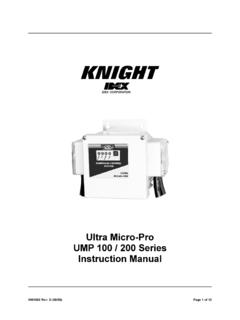
2 If any questions arise, contact Cutler-Hammer for further information or INTRODUCTIONThe N-frame Series C circuit breaker (Fig. 1-1) types ND, HND and NDC are 600 VAC maximum rated devices, with integral trip units and interchangeable Rating Plugs. Two continuous current ratings are available 400-800 Amp and 600-1200 Amp. Refer to table 1-1 for available trip units and table 1-2 for available rating plugs. Model D circuit breakers are listed in accordance with Underwrit-ers Laboratories, Inc. Standard UL-489 and satisfy the requirements of the International Electrotechnical Com-mission Recommendations No. IEC 947-2. Molded case switches are listed in accordance with UL 1-1N-frame Series C circuit BreakerThe Digitrip RMS 310 Trip Units are AC only devices that employ microprocessor based technology that provides true RMS current sensing means for proper correlation with thermal characteristics of conductors and equip-ment.
3 The primary function of the Trip Unit is circuit pro-tection. This is achieved by analyzing the secondary current signals received from the circuit breaker current sensors and initiating trip signals to the circuit breaker shunt trip when pre-set current levels and time delay set-tings are exceeded. Low level ground fault protection with an adjustable time delay is supplied when appropriate trip types are open air at 40 C, an N-frame circuit breaker with a Dig-itrip 310 trip unit will carry continuously up to 1200 amperes without exceeding a 50 C rise at the terminals. The calibration of the trip unit is insensitive to ambient temperatures over a range of -20 to +55 C. However, the trip unit contains thermal temperature protective circuitry that initiates a trip operation for self-protection if the inter-nal ambient temperature at the printed circuit board (PCB) reaches approximately 90 C.
4 For ambient condi-tions above 40 C, derating of the circuit breaker should be considered to avoid exceeding a safe terminal temper-WARNINGI nstructions for ND, CND, HND, CHND, NDC and CNDCC ircuit Breakers and N-frame Series C Molded Case 29C106 FEffective September 1999 Page 2ature operating range. Consult Cutler-Hammer for Case Switches: The Molded Case switch is similar to the circuit Breaker except that it does not have a replaceable rating plug and has a different tripping characteristic. There is a fixed instantaneous trip at 15,000 Ampere but there is no overload short delay or ground fault trip. As a result sections , , 4, 5, and 7 are not applicable. In the remaining sections the term circuit breaker shall also include the molded case switch .
5 100 Percent Rated N-Frame circuit Breaker: CND, CHND and CNDC circuit breakers are suitable for contin-uous operation at 100 percent of the frame rating in an enclosure which measures at least 42 height, 22 3/4 width and 11 1/2 depth. The 800A version requires no ventilation. The 1200A version requires 224 inch2 ventila-tion on the front face of the enclosure (72 sq. in. top, 72 sq. in. bottom, 40 sq. in. left and 40 sq. in. right). Further-more the 1200A version has to be used with the supplied conductor extensions and terminal barriers as shown in Figure 2-2. Use only 90 C rated wire with ampacity based on 75 C rated conductors. Use Copper only or AL9CU terminals only. Overload Trip: In accordance with standards require-ments, the trip unit initiates a trip of the circuit breaker within two hours for an overload of 135 percent, and a trip in less time for higher Thermal Memory effect prevents the breaker from being re-energized immediately after an overload.
6 A cooling off period of up to 5 minutes is required, which allows time for cabling to cool delay/Instantaneous Trip: For short circuit condi-tions that exceed the short delay pick-up settings, the trip units initiates a trip after a delay prescribed by the I2t ramp function for trip units designated T33 and T35. A flat response time delay action is provided by trip units desig-nated T32 and T36 unless the instantaneous (I) setting is selected. Fixed rating plugs available, see table 1-2. Optional four-setting adjustable rating plugs available, see table 1-2. Using trip unit with adjustable delay (T32, T36), instantaneous pick-up is achieved when the lowest time delay set-ting (I) is selected. Override setting fixed at frame withstand 1-1: ELECTRONIC (DIGITRIP 310) TRIP UNIT TYPESTrip Unit FunctionsDigitrip RMS 310 Trip UnitT33T32T35T36 KLong TimeFixed Ampere Rating with Fixed Long DelayAdjustable Ampere Setting with Fixed Long Delay Short TimeAdjustable Short Time Pick-up with Short Time Delay I2t RampAdjustable Short Time Delay with Adjustable Short Time Pick-up, or Adjustable Instantaneous Pick-up Instantaneous Fixed Instantaneous (Override) Ground Fault Adjustable Ground Fault Pick-up with Adjustable Ground Fault Time 29C106 FEffective September 1999 Page 3 Not UL listed Occurs with short delay time adjustment set at I.
7 The Molded Case switch has a fixed non-interchangeable rating plugGround Fault Protection: When selected, ground fault pick-up and time delay settings shown in Table 1-2 allow selective ground fault coordination with other circuit pro-tection devices. Ground Fault Alarm Unit: A ground fault alarm unit may be used with the trip unit to provide visual indication and a contact closure when a ground fault trip occurs. The ground fault trip alarm unit is ordered and shipped sepa-rately if required. DC Application: Digitrip 310 trip units are suitable for AC application Testing: Test points are available for functional field testing of the trip unit when connected to test kit (Catalog No. STK2).Internal Accessories: Internal accessories mount on the Digitrip trip unit.
8 A list of internal accessories and their instruction leaflets is provided below: Alarm (Signal)/Lockout (ASL) 29C184 Auxiliary 29C124 Shunt 29C148 Low Energy Shunt 29C145 Undervoltage Release Mechanism (Handle Reset) 29C174 Note: Shunt trip and undervoltage accessories, if required, must be mounted in the left : Digitrip 310 trip unit versions with ground fault protection are supplied with an auxiliary switch , mounted in the right pole of the trip 1-2: ELECTRONIC (DIGITRIP 310) TRIP UNIT FUNCTION AND RATING SENSINGTrip FunctionRating/Setting Description Ampere RatingFixed at 100%Fixed rating plugs availableTrip Unit Ampere RatingFixed Rating Plugs1200 Amp800 Amp600, 630 , 700, 800, 1000, 1200, 1250 A (In)400, 450, 500, 550, 600, 630 , 700, 800A (In)Adjustable Long Time Pick-upAdjustable rating plugs available Trip Unit Ampere Rating Adjustable Rating Plugs1200 Amp800 Amp600,800,1000,1200A (In) 400,500,600,800A (In)Short Delay Pick-up (Adjustable)In multiples of installed rating plug amperes (In) with marks at 2-3-4-5-6-7-8xShort Delay Time (Fixed)I2t ramp configurationShort Delay Time (Adjustable)
9 Flat response with time delay settings at 100 ms, 200 ms, and 300 msInstantaneous Pick-up In multiples of installed rating plug amperes (In) with marks at 2-3-4-5-6-7-8xGround Fault Pick-up (adjustable)Trip Unit Ampere RatingTrip Unit Setting1200 Amp800 Amp200, 400, 600, 800, 1000 and 1200 Amp200, 400, 600, 800, 1000 and 1200 AmpGround Fault Time DelaySettings at instantaneous (I) 150 ms, 300 ms, and 500 29C106 FEffective September 1999 Page 4 This instruction leaflet gives procedures for installation and field testing of N-frame Series C circuit breakers and describes the different trip unit characteristics. For this publication, the term circuit breaker shall also include the molded case INSTALLATIONThe installation procedure consists of inspecting the cir-cuit breaker, installing the accessories and terminals if required, mounting the circuit breaker, connecting the line and load conductors and accessory wiring, adjusting the trip settings, and installing the rating plug.
10 circuit break-ers, accessories, terminals, and rating plugs may be sup-plied in separate packages. To install the circuit breaker, perform the following InspectionMake sure that the circuit breaker is suitable for the intended installation by comparing nameplate data with existing equipment ratings and system requirements. Inspect the circuit breaker for completeness and check for damage before Accessory InstallationNote: If required, internal accessory installation in any type of circuit breaker should be done before the circuit breaker is mounted and connected. Refer to the individual accessory instruction leaflets listed accessories per the accessory instruction BREAKER COVER CONSTRAINS MOVING PARTS. DO NOT OPERATE THE BREAKER WITH-OUT THE COVER Terminal Installation100 Percent Rated N-Frame: Connect the supplied line and load conductor extensions as shown in Fig.