Transcription of INTEGRAL™ Self-Protected Combination Motor Controllers
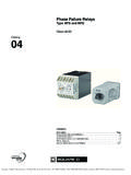
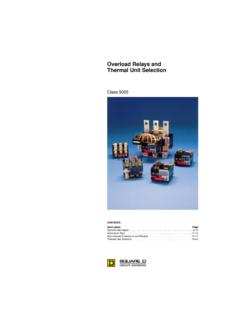
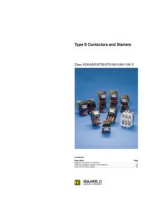
1 Schneider Electric Brands INTEGRAL Self-Protected Combination Motor Controllers Class 8539 CONTENTSD escriptionPage Product Descriptions.. 3-5 Selection .. 6-20 Application and General Information.. 21-27 Specifications .. 28-41 Wiring Diagrams .. 42-46 Dimensions .. 47-51 INTEGRAL Self-Protected Combination Motor Controllers 2000 Schneider Electric All Rights Reserved 2 01/00 INTEGRAL Self-Protected Combination Motor Controllers Product Description 3 01/00 2000 Schneider Electric All Rights Reserved Combination Motor CONTROL IN ONE COMPACT PACKAGE! The INTEGRAL Self-Protected Combination Motor controller (CMC) combines all the functions of a disconnect, circuit breaker, contactor, and overload relay in a coordinated Motor controller . A wide variety of easy-to-install auxiliary blocks and interface modules provides powerful communication and control much as 60% less panel space is required by the INTEGRAL CMC as compared to traditional Combination Motor control circuit installations.
2 In addition, installation and wiring time is dramatically reduced simply snap the INTEGRAL onto a 35 mm DIN rail and connect load and line side entire family of INTEGRAL CMCs have proven their reliability and effectiveness in thousands of applications worldwide. By installing the INTEGRAL Self-Protected CMC, you are implementing the latest in Motor control and protection technology, and assuring the lowest installed cost of any Motor control scheme. Features Non-reversing and reversing Combination Motor Controllers available in 18, 32, or 63 ampere ratings. NEMA Type 1 and 12 enclosed Combination Motor Controllers and open style Combination Motor Controllers both available. Current-limiting short-circuit protection provides 42 kA interrupt rating. UL listed as a Type E Combination Motor controller . UL verified to meet Type 2 coordination protection per IEC 947-4.
3 Meets Total Coordination requirements of IEC 947-6 no damage to contactor or overload relay, and no welding of contacts after interruption of short-circuit faults. Padlockable isolation knob. Minimum million operation life expectancy. Proven reliability even after exposure to multiple short-circuit faults! Control direct from PLC or PC with optional interface 18 Integral 32 Integral 63 INTEGRAL Self-Protected Combination Motor Controllers Product Description 2000 Schneider Electric All Rights Reserved 4 01/00 INTEGRAL 18 INTEGRAL 32LD1LB030 LD5LB030 + +LB1LB03P LB1LB03P LD1LC030 LD4LC030 LD5LC130 + ++LB1LC03M LB1LC03M LB1LC03M Rated Operational Current for AC-3 Duty 18 A32 A Rated Breaking Capacity 42 KA at 480 Vac42 KA at 480 Vac Approvals ASTA, BS, CSA, DEMKO, IEC, NEMKO, SEMKO, UL, VDEASTA, BS, CSA, DEMKO, IEC, NEMKO, SEMKO, UL.
4 VDE Number of Poles 33 Protection Module LB1LB03P LB1LC03M Magnetic Protection Fixed, 15 times maximum thermal currentAdjustable, 6 to 12 times maximum thermal current Overload Protection to A: P01 to A P02 to A P03 to A M03 to A P04 to A M04 to A P05 to A M05 to A P06 to A M06 to A P07 to A M07 to A P08 to A M08 to A P10 to A M10 to A P13 to A M13 to A P17 to A P17 to A P21 to A M22 to A M23 INTEGRAL Self-Protected Combination Motor Controllers Product Description 5 01/00 2000 Schneider Electric All Rights Reserved INTEGRAL 63LD1LC030 LD4LC030 LD5LC130 + ++LB1LC03M LB1LC03M LB1LC03M Rated Operational Current for AC-3 Duty 63 A Rated Breaking Capacity 42 KA at 480 Vac Approvals ASTA, BS, CSA, DEMKO, IEC, NEMKO, SEMKO, UL, VDE Number of Poles 3 Protection Module LB1LD03M Magnetic Protection Adjustable.
5 6 to 12 times maximum thermal current Overload Protection to A M16 to A M21 to A M22 to A M53 to A M55 to A M57 to A M61 INTEGRAL Self-Protected Combination Motor Controllers Selection 2000 Schneider Electric All Rights Reserved 6 01/00 To order an INTEGRAL CMC, complete these four steps: 1. Select the correct Combination Motor controller from Table 1A (open) or Table 1B (enclosed). 2. Complete the catalog number by adding the coil voltage code from Table Choose the appropriate protection module from Table 3. 4. For enclosed Combination Motor Controllers only, select any desired INSTA-KITS or factory modifications from Table on page 20. For factory modification, add the form number to the end of the catalog number. l Complete the catalog number by adding the voltage code from Table 2 n INTEGRAL Base Units ordered with DC voltage code (BD, ED or FD) are shipped with LA1L*080*D Voltage Converter Module already installed.
6 Open INTEGRAL CMC Dimensions .. page 48 Enclosed INTEGRAL CMC Dimensions .. page 51 Table 1A: Open Style INTEGRAL CMC Base Unit Selection Table Continuous Current Rating Maximum 3-Phase HP RatingWith IsolatorWithout IsolatorAmperes 230 V460 V575 VCatalog Number Catalog Number Non-Reversing 1851015LD1LB030*N/A32102030LD4LC030*LD1L C030 l 63204060LD4LD030*LD1LD030 l Reversing 1851015LD5LB130*N/A32102030LD5LC030*N/A6 3204060LD5LD030*N/A Table 1B: Enclosed INTEGRAL CMC Selection Table Continuous Current Rating Maximum 3-Phase HP RatingType 1 EnclosureType 12 EnclosureAmperes 230 V460 V575 VCatalog Number Catalog Number Non-Reversing 1851015LE1UI1846 l LE1UI1847 l 32102020LE1UI3246 l LE1UI3247 l 63204060LE1UI6346 l LE1UI6347 l Reversing 1851015LE2UI1846 l LE2UI1847 l 32102020LE2UI3246 l LE2UI3247
7 L 63204060LE2UI6346 l LE2UI6347 l Table 2: Coil Voltage Codes Control VoltageINTEGRALF requency Hz2448110120220240380415480600I18 50 BE F - MUQN - -60 BCDKFCLCMC--NSDC n BD--------- I32 50 BE F - MUQN - -60 BCDFCFCMCMC--QSDC n BDEDFD------- I63 50 BE F - MUQN - -60 BCCEKFCLCMC--QSDC n BDEDFD-------LD1LB030 LD5LB130 LD4LC030 LD5LC030 LD4LD030 Open Product File E164871 CCN NKJHNKJH7 File LR 43364 Class 3211 08 Enclosed Product File E163364 CCN NKJHNKJH7 File LR 105062 Class 3211 08 INTEGRAL Self-Protected Combination Motor Controllers Selection 7 01/00 2000 Schneider Electric All Rights Reserved c Thermal settings are based on motors with a service factor ( ) of Table 3.
8 Overload Protection Modules (Class 10, Ambient Compensated) Thermal Setting Range, Amperes c Magnetic Setting Range, Amperes Standard Module with Thermal & Magnetic TripCatalog onlyModuleFor 18 Ampere models - LB1LB03P01 - LB1LB03P02 - LB1LB03P03 - LB1LB03P04 - 1 LB1LB03P05N/A1 - LB1LB03P06 - LB1LB03P07 - 4 LB1LB03P08N/A4 - 6 LB1LB03P10N/A6 - 10 LB1LB03P13N/A10 - 16 LB1LB03P17N/A12 - 18 LB1LB03P21N/A For 32 Ampere models - - - - - - - - - - - - - - - 1060 - 120LB1LC03M13LB6LC03M1310 - 1695 - 190LB1LC03M17LB6LC03M1716 - 25150 - 300LB1LC03M22LB6LC03M2223 - 32190 - 380LB1LC03M53LB6LC03M53 For 63 Ampere models 18 - 25150 - 300LB1LD03M22LB6LD03M2223 - 32190 - 380LB1LD03M53LB6LD03M5328 - 40240 - 480LB1LD03M55LB6LD03M5535 - 50300 - 600LB1LD03M57LB6LD03M5745 - 63380 - 760LB1LD03M61LB6LD03M61 Specifications Operating Positions.
9 UL Listed and CSA certifiedConforms to IEC standardsShock resistance - 8 g (Duration of impulse: 11 ms) Vibration resistance - 3 g (5 to 150 Hz) AC control circuit temperature limits: Storage -40 to +176 F/-40 to +80 CRated voltage - 600 VacOperation -13 to +104 F/-25 to +70 C Rated thermal current - 18 A (INTEGRAL 18), 32 A (INTEGRAL 32), 63 A (INTEGRAL 63)Interrupting current at 480 Vac: 42 kA ms Fixed magnetic trip is set at approximately 15 times full load current (FLC)INTEGRAL 18 INTEGRAL 32 INTEGRAL 63 Mechanical life: 20 million operations 10 million operations 5 million operations Operating current of magnetic trip is approximately15 times maximum thermal trip (non-adjustable setting)File E164871 CCN NKJHNKJH7 File LR 43364 Class 3211 08LB1LB03P05 LB1LC03M22 LB1LD03M57 30 30 90 90 INTEGRAL Self-Protected Combination Motor Controllers INTEGRAL 18 Accessories 2000 Schneider Electric All Rights Reserved 8 01/00LD5 LBAUTOOTRIP.
10 +LA1LB021 LA1LB019LA1LB0211 LA1LB017 LA1LB015 AUTOOTRIP. +LD1 LBAUTOOTRIP. +LA1LB001LA1LB0311 LA1LB034 LA1LB031 LA1LB0341 LA1LB001 INTEGRAL Self-Protected Combination Motor Controllers INTEGRAL 18 Accessories 9 01/00 2000 Schneider Electric All Rights Reserved a Use of auxiliary contact LA1LB001 requires Combination with contact block LA1LB015, LA1LB021, LA1LB017, or LA1LB019. Auxiliary Contact Blocks for the INTEGRAL 18 CMC For Use On Mounting LocationType and Number of Contacts per BlockContact TypeCatalog Number LD1 or LD5 Right SideBlock of 5 instantaneous contacts 3 signal contactor state 2 signal tripped status2 N/O + 1 N/C 1 N/O + 1 N/CLA1LB015 Right SideBlock of 3 instantaneous contacts 2 signal contactor state 1 signal tripped status1 N/O + 1 N/C 1 N/OLA1LB017 Right SideBlock of 3 instantaneous contacts 2 signal contactor state 1 signal tripped status1 N/O + 1 N/C 1 N/CLA1LB019 Left or Right SideComplementary auxiliary block 1 signal contactor state 1 N/CLA1LB001 a LD1 Left Side2 signal operating handle not in Auto position2 N/OLA1LB031 Left Side2 signal operating handle not in Auto position1 N/O + 1 N/CLA1LB0311 Left SideBlock of 3 instantaneous contacts 2 signal operating handle not in Auto position 2