Transcription of Introduction • SPI Pin Functionality Features
1 Atmel AVR 8-bit Microcontroller AVR151: Setup and Use of the SPI APPLICATION NOTEI ntroductionThis application note describes how to set up and use the on-chip SerialPeripheral Interface (SPI) of the Atmel AVR microcontroller. Most AVRdevices come with an on board SPI and can be configured according to thisdocument. This document contains, theoretical background and the steps toconfigure the SPI to run in both master mode and slave SPI Pin Functionality Multi Slave Systems SPI Timing SPI Transmission Conflicts Emulating the SPI Code examples for Polled operation Code examples for Interrupt Controlled operationAtmel-2585D-Setup-and-Use-of-th e-SPI_AVR151_Application Note-02/2016 Table of Description of the Transmission Between Master and of the Slave Systems - SS Pin For High Speed Transmission the 1: SPI Communication Controlled by 2: SPI Communication Controlled by AVR151.
2 Setup and Use of the SPI [APPLICATION NOTE]Atmel-2585D-Setup-and-Use-of-the-SP I_AVR151_Application Note-02/201621. General Description of the SPIThe SPI allows high-speed synchronous data transfer between the AVR and peripheral devices orbetween several AVR devices. On most parts the SPI has a second purpose where it is used for InSystem Programming (ISP). Refer to the AVR910 application note for 1-1. Master and Slave InterfaceThe interconnection between two SPI devices always happens between a master device and a slavedevice. Compared to some peripheral devices like sensors, which can only run in slave mode, the SPI ofthe AVR can be configured for both master and slave mode.
3 The mode the AVR is running in is specifiedby the settings of the master bit (MSTR) in the SPI control register (SPCR). Special considerations aboutthe SS pin have to be taken into account. This is described in Multi Slave Systems - SS Pin Functionalityon page master is the active part in this system and has to provide the clock signal a serial data transmissionis based on. The slave is not capable of generating the clock signal and thus can not get active on itsown. The slave just sends and receives data, if the master generates the necessary clock signal. Themaster, however, generates the clock signal only while sending data.
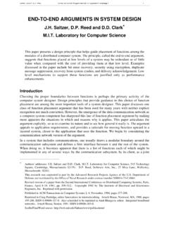
4 That means the master has to senddata to the slave to read data from the Data Transmission Between Master and SlaveThe interaction between a master and a slave AVR is shown in Figure 1-1 Master and Slave Interface onpage 3. Two identical SPI units are displayed. The left unit is configured as master while the right unit isconfigured as slave. The MISO, MOSI, and SCK lines are connected with the corresponding lines of theother part. The mode in which a part is running determines if they are input or output signal a bit is shifted from the master to the slave and from the slave to the master simultaneously inone clock cycle both 8-bit shift registers can be considered as one 16-bit circular shift register.
5 Thismeans that after eight SCK clock pulses the data between master and slave will be AVR151: Setup and Use of the SPI [APPLICATION NOTE]Atmel-2585D-Setup-and-Use-of-the-SP I_AVR151_Application Note-02/20163 The system is single buffered in the transmit direction and double buffered in the receive direction. Thisinfluences the data handling in the following ways:1. New bytes to be sent cannot be written to the data register (SPDR) / shift register before the entireshift cycle is Received bytes are written to the Receive buffer immediately after the transmission is The Receive buffer has to be read before the next transmission is completed or data will be Reading the SPDR will return the data of the Receive a transfer is completed the SPI Interrupt Flag (SPIF) will be set in the SPI Status Register (SPSR).
6 This will cause the corresponding interrupt to be executed if this interrupt and the global interrupts areenabled. Setting the SPI Interrupt Enable (SPIE) bit in the SPCR enables the interrupt of the SPI whilesetting the I bit in the SREG enables the global Pins of the SPIThe SPI consists of four different signal lines. These lines are the shift clock (SCK), the Master Out SlaveIn line (MOSI), the Master In Slave Out line (MISO) and the active low Slave Select line (SS). When theSPI is enabled, the data direction of the MOSI, MISO, SCK, and SS pins are overridden according to thefollowing 1-1. SPI Pin OverridesPinDirection Master ModeDirection Slave ModeMOSIUser DefinedInputMISOI nputUser DefinedSCKUser DefinedInputSSUser DefinedInputThis table shows that the input pins are automatically configured.
7 The output pins must be initializedmanually by the software. The reason for this is to avoid damages through driver Multi Slave Systems - SS Pin FunctionalityThe Slave Select (SS) pin plays a central role in the SPI configuration. Depending on the mode the part isrunning in and the configuration of this pin, it can be used to activate or deactivate the devices. The SSpin can be compared with a chip select pin which has some extra master mode, the SS pin must be held high to ensure master SPI operation if this pin is configured asan input pin. A low level will switch the SPI into slave mode and the hardware of the SPI will perform thefollowing actions:1.
8 The master bit (MSTR) in the SPI Control Register (SPCR) is cleared and the SPI system becomesa slave. The direction of the pins will be switched according to Table 1-2 Overview of the SS PinFunctionality on page The SPI Interrupt Flag (SPIF) in the SPI Status Register (SPSR) will be set. If the SPI interrupt andthe global interrupts are enabled the interrupt routine will be can be useful in systems with more than one master to avoid two masters accessing the SPI bus atthe same time. If the SS pin is configured as output pin it can be used as a general purpose output pinwhich does not affect the SPI AVR151: Setup and Use of the SPI [APPLICATION NOTE]Atmel-2585D-Setup-and-Use-of-the-SP I_AVR151_Application Note-02/20164 Note: In cases where the AVR is configured for master mode and it can not be ensured that the SS pinwill stay high between two transmissions, the status of the MSTR bit has to be checked before a new byteis written.
9 After the MSTR bit has been cleared by a low level on the SS line, it must be set by theapplication to re-enable SPI master slave mode the SS pin is always an input. When SS is held low, the SPI is activated and MISO becomes output if configured so by the user. All other pins are inputs. When SS is driven high, all pins areinputs, and the SPI is passive, which means that it will not receive incoming data. The following tableshows an overview of the SS Pin 1-2. Overview of the SS Pin FunctionalityModeSS ConfigurationSS Pin-levelDescriptionSlaveAlways InputHighSlave deactivated (deselected)LowSlave activated (selected)MasterInputHighMaster activated (selected)LowMaster deactivated, switched toslave modeOutputHighMaster activated (selected)LowNote: In slave mode, the SPI logic will be reset once the SS pin is brought high.
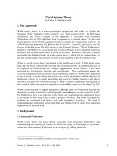
10 If the SS pin is broughthigh during a transmission, the SPI will stop sending and receiving immediately and both data receivedand data sent must be considered as shown in the preceding table , the SS pin in slave mode is always an input pin. A low level activatesthe SPI of the device while a high level causes its deactivation. A Single Master Multiple Slave Systemwith an AVR configured in master mode and SS configured as output pin is shown in the following amount of slaves which can be connected to this AVR is only limited by the number of I/O pins togenerate the slave select AVR151: Setup and Use of the SPI [APPLICATION NOTE]Atmel-2585D-Setup-and-Use-of-the-SP I_AVR151_Application Note-02/20165 Figure 1-2.