Transcription of Inverter MICROMASTER 440 - paratrasnet
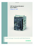
1 Siemens DA 2007/20084/14 InverterMICROMASTER 4404/2 Description4/4 Circuit diagrams4/6 Technical data4/9 Selection and ordering data4/12 Options4/26 Dimension drawings Siemens AG 20074/2 Siemens DA 2007/2008 MICROMASTER 4404nApplicationnDesignnMain characteristicsnEasy, guided start-upnModular construction al-lows maximum configura-tion flexibilitynSix programmable isolated digital inputs nTwo scaleable analog in-puts (0 V to 10 V, 0 mA to 20 mA) can also be used as a 7th/8th digital inputnTwo programmable analog outputs (0 mA to 20 mA)nThree programmable relay outputs (30 V DC/5 A resis-tive load; 250 V AC/2A in-ductive load)nLow-noise motor operation thanks to high pulse fre-quencies, adjustable (ob-serve derating if necessary)nComplete protection for motor and (overview)nEMC filter, Class A/BnLC filter and sinusoidal filternLine commutating chokesnOutput chokesnGland platesnBasic Operator Panel (BOP) for parameterizing the inverternPlain text Advanced Opera-tor Panel (AOP) with multi-language displaynPlain text Asian Advanced Operator Panel (AAOP) with Chinese and English displaynPlain text Cyrillic Advanced Operator Panel (CAOP) with Cyrillic, German and English displaynCommunication modules PROFIBUS DeviceNet CANopennPulse encoder evaluation modulenPC connection kitsnMounting kits for installing the operator panels in the control cabinet doorsnPC start-up tools execut-able under Windows 98 and NT/2000/ME/XP ProfessionalnTIA integration with Drive MICROMASTER 440 in-verter is suitable for a variety of variable-speed drive appli-cations.
2 Its flexibility provides for a wide spectrum of appli-cations. These also include cranes and hoisting gear, high-bay warehouses, pro-duction machines for food, beverages and tobacco, packaging machines etc.; applications which require the frequency Inverter to have a higher functionality and dy-namic response than Inverter is especially char-acterized by its customer-ori-ented performance and ease-of-use. Its large mains voltage range enables it to be used all over the MICROMASTER 440 in-verter has a modular design. The operator panels and mod-ules can be easily standardsnThe MICROMASTER 440 Inverter complies with the requirements of the EU low-voltage guidelinenThe MICROMASTER 440 Inverter has the > mark-ingnacc. to u and cu certifiednc-tick l4 Note:nSee Appendix for Siemens AG 2007 Siemens DA 2007/20084/3 MICROMASTER 4404nMechanical featuresnPerformance featuresnProtection featuresnModular designnOperating kW to 75 kW: 10 C to +50 C(+14 F to +122 F)90 kW to 200 kW.
3 0 C to +40 C(+32 F to +104 F)nCompact housing as a re-sult of high power densitynEasy cable connection, mains and motor connec-tions are separated for opti-mum electromagnetic com-patibilitynDetachable operator panelsnScrewless control terminals on detachable I/O IGBT technologynDigital microprocessor controlnHigh-quality Vector Control systemnFlux Current Control (FCC) for improved dynamic re-sponse and optimized mo-tor controlnLinear V/f characteristicnQuadratic V/f characteristicnMultipoint characteristic (programmable V/f charac-teristic)nTorque controlnFlying restartnSlip compensationnAutomatic restart following mains failure or faultnUser-definable function blocks for logic and arith-metic operationsnKinetic bufferingnPositioning ramp downnHigh-grade PID controller for simple internal process control (autotuning)nProgrammable accelera-tion/deceleration, 0 s to 650 snRamp smoothingnFast Current Limit (FCL) for trip-free operationnFast, repeatable digital in-put response timenFine adjustment using two high-resolution 10-bit ana-log inputsnCompound braking for con-trolled rapid brakingnIntegrated brake chopper (for kW to 75 kW invert-ers)nFour skip frequenciesnRemovable Y capacitor for use on IT systems (with non-grounded mains sup-plies, the Y capacitor must be removed and an output choke installed).
4 NOverload capability CT kW to 75 kW:Overload current x rated output current ( 150 % overload capabili-ty) for 60 s, cycle time 300 s, and 2 x rated out-put current ( 200 % overload capability) for 3 s, cycle time 300 s90 kW to 200 kW:Overload current x rated output current ( 136 % overload capabili-ty) for 57 s, cycle time 300 s, and x rated out-put current ( 160 % overload capability) for 3 s, cycle time 300 s VT kW to 90 kW:Overload current x rated output current ( 140 % overload capabili-ty) for 3 s, and x rated output current ( 110 % overload capability) for 60 s, cycle time 300 s110 kW to 250 kW:Overload current x rated output current ( 150 % overload capabili-ty) for 1 s, and x rated output current ( 110 % overload capability) for 59 s, cycle time 300 snOvervoltage/undervoltage protectionnInverter overtemperature protectionnSpecial direct connection for PTC or KTY to protect the motornEarth fault protectionnShort-circuit protectionnI2t motor thermal protectionnLocked motor protectionnStall preventionnParameter Siemens AG 20074/4 Siemens DA 2007/2008 MICROMASTER 4404nGeneral circuit diagram=3~ADADPEPE U, V, WM1 2 ADC ADC1 2A/DA/D+ 10 V0 V NPNPNPDCNADCNSDCPSDCPADC-~=ADC1+ADC2+ADC 2-ADC1-DIN1 DIN2 DIN3 DIN4 DIN5 DIN6 PTCAPTCBDAC1+DAC2+DAC2-DAC1-P+N-COMCOMCO MNCNONONONC12341011567816179281415121326 27293020181925232422210 - 20 mAmax.
5 5000 - 20 mAmax. 500 0 - 20 mA0 - 10 V5678161728 DIN1 DIN2 DIN3 DIN4 DIN5 DIN6 24 V +_ADADRS485 PESI1 260 Hz 50 Hz ~=CPU1/3 AC 200 - 240 V3 AC 380 - 480 V3 AC 500 - 640 VB+/DC+DC-B-R4,7 kL/L1, N/L2, L/L1, N/L2, L3L1, L2, L3orMotor30 V DC/5 A (resistive load) 250 V AC/2 A (inductive load)Frame sizesA to FFrame sizesFX and GXmax. 100 mA( isolated )Output +24 Vmax. 100 mA( isolated )Output 0 VcurrentvoltageautomaticTerminalforexter nalbrake unitNotusedDIP switch(on control board)DIPswitchon I/OboardOpto isolationG_DA51_EN_05024hororTerminalfor dv/dt FilterCOM linkCBoptionRelay 3 Relay 2 Relay 124 V externalBOP linkPTC/KTY 84 Circuit diagrams Siemens AG 2007 Siemens DA 2007/20084/5 MICROMASTER 4404nTerminal connection diagram222425231820211927293028181726161 21415138101196751342RL1-ARL2-BRL1-BRL1-C RL2-CRL3-ARL3-BRL3-CDAC1+ DAC1- P+N-DIN5 DIN6 DAC2+ DAC2-PTCAPTCBPE0 V+10 V0 VADC1+ADC1-DIN1 DIN2 DIN3 DIN4 ADC2+ ADC2-+24 VS2S1(DIN7)(DIN8)AIN1 AIN2 NPN *)PNP *)DIP Switches.
6 0 mA to 20 mA or0 V to 10 VOutput relay contactsAnalog output 1 Digital inputsAnalog output 2RS-485(USS-protocol)Voltagesupply 10 VDigital inputsAnalog input 1 Analog input 2*) PNP or NPN possible G_DA51_EN_05107 View AMotor connectionsExample, frame size FXView AMains connectionsCircuit diagrams Siemens AG 20074/6 Siemens DA 2007/2008 MICROMASTER 4404nMICROMASTER 440 inverterMains voltage and power ranges1 AC 200 V to 240 V 10 %3 AC 200 V to 240 V 10 %3 AC 380 V to 480 V 10 %3 AC 500 V to 600 V 10 %CT (constant torque) kW to 3 kW to 45 kW to 200 kW to 75 kWVT (variable torque) kW to 55 kW to 250 kW to 90 kWInput frequency47 Hz to 63 kW to 75 kWfrequency90 kW to 200 kW0 Hz to 650 Hz (in V/f mode)0 Hz to 267 Hz (in V/f mode)0 Hz to 200 Hz (in vector mode)0 Hz to 200 Hz (in vector mode)Power factor kW to 75 kW: 96 % to 97 %; 90 kW to 200 kW: 97 % to 98 % (Further information is available on the Internet at: )Overload capability CT kW to 75 kW90 kW to 200 kW VT kW to 90 kW110 kW to 250 kWOverload current x rated output current ( 150 % overload capability) for 60 s, cycle time 300 s and 2 x rated output current ( 200 % overload capability) for 3 s, cycle time 300 s Overload current x rated output current ( 136 % overload capability) for 57 s, cycle time 300 s and x rated output current ( 160 % overload capability) for 3 s, cycle time 300 s Overload current x rated output current ( 140 % overload capability) for 3 s,and x rated output current ( 110 % overload capability) for 60 s, cycle time 300 s Overload current x rated output current ( 150 % overload capability) for 1 s,and x rated output current ( 110 % overload capability) for 59 s, cycle time 300 s Inrush currentnot higher than rated input currentControl methodVector control, torque control, linear V/f characteristic; quadratic V/f characteristic.
7 Multipoint characteristic (programmable V/f characteristic); flux current control (FCC)Pulse frequency kW to 75 kW90 kW to 200 kW4 kHz (standard); 16 kHz (standard with 230 V inverters kW to kW)2 kHz to 16 kHz (in 2 kHz steps)2 kHz (standard with VT mode); 4 kHz (standard with CT mode)2 kHz to 4 kHz (in 2 kHz steps)Fixed frequencies15, programmableSkip frequency ranges4, programmableSetpoint Hz digital; Hz serial; 10 bit analogDigital inputs6 fully programmable isolated digital inputs; switchable PNP/NPNA nalog inputs2 programmable analog inputs 0 V to 10 V, 0 mA to 20 mA and 10 V to +10 V (AIN1) 0 V to 10 V and 0 mA to 20 mA (AIN2) both can be used as 7th/8th digital inputRelay outputs3, programmable, 30 V DC/5 A (resistive load); 250 V AC/2A (inductive load)Analog outputs2, programmable (0/4 mA to 20 mA)Serial interfacesRS-485, optional RS-232 Motor cable without output chokelengthswith output 75 kW:max. 50 m (shielded), max. 100 m (unshielded)90 250 kW:max.
8 200 m (shielded), max. 300 m (unshielded)see variant dependent optionsElectromagnetic compatibility (see Selection and Ordering Data)EMC filter, Class A or Class B to EN 55 011 available as an optionInverter with internal filter Class A availableBrakingResistance braking with DC braking, compound braking, integrated brake chopper (integrated brake chopper only with kW to 75 kW inverters)Degree of protectionIP20 Operating kW to 75 kWtemperature(without derating)90 kW to 200 kWCT: 10 C to +50 C (+14 F to +122 F)VT: 10 C to +40 C (+14 F to +104 F)0 C to +40 C (+32 F to +104 F)Storage temperature 40 C to + 70 C ( 40 F to +158 F)Relative humidity95% (non-condensing)Installation altitude kW to 75 kW90 kW to 200 kWup to 1000 m above sea level without deratingup to 2000 m above sea level without deratingStandard SCCR (Short Circuit Current Rating) 1)FSA, FSB, FSC: 10 kAFSD, FSE, FSF, FSFX, FSGX: 42 kAProtection features forUndervoltage, overvoltage, overload, earth faults, short-circuits, stall prevention, locked motor protection, motor over-temperature, Inverter overtemperature, parameter change protectionCompliance with standardsu, cu, >, c-tick l4> markingConformity with low-voltage directive 73/23/EECC ooling-air volumetric flow required, dimensions and weights (without options)Frame size (FS)A BCDE F without filterF with filterFXGXC ooling-air volumetric flow required (l/s)/(CFM) x x x x x W x D, max.
9 (mm)173 x 73 x 149202 x 149 x 172245 x 185 x 195520 x 275 x 245650 x 275 x 245850 x 350 x 3201150 x 350 x 3201400 x 326 x 3561533 x 326 x 545 Weight, approx. (kg) ) For footnote, see page 4 : Cubic Feet per MinuteTechnical data Siemens AG 2007 Siemens DA 2007/20084/7 MICROMASTER 4404nDerating dataPulse frequencyOutputRated output current in Afor a pulse frequency ofkW4 kHz6 kHz8 kHz10 kHz12 kHz14 kHz16 kHzMains voltage 1/3 AC 200 to correspond to the 4 kHz standard derating, since 16 kHz operating voltage 3 AC 400 Mains operating voltage 3 AC 500 ) Applies to industrial control cabinet installations to NEC article 409/UL 508A. For further information, visit us on the Internet at: data Siemens AG 20074/8 Siemens DA 2007/2008 MICROMASTER 4404nDerating data (continued)Operating temperatureInstallation altitude above sea level406000204080DA51-5047a10010%55 C85203045 Rated output currentOperating temperatureA3060-1007002040208010010%605 040 CCTVT7050 Rated output currentOperating temperatureG_DA51_EN_05026cInverter kW to 75 kWInverter 90 kW to 200 kW200060040000204080DA51-50461001000%300 0 m85 Rated output currentOperational altitudeA200060040000204080DA51-5018c100 1000%3000 mRated output currentOperational altitudeAInverter kW to 75 kWInverter 90 kW to 200 kWPermissible output currentin % of the rated output current200060040000204080DA51-5019b10010 00%3000 m77 Mains voltageOperational altitudeA200060040000204080DA51-5019b100 1000%3000 m77 Mains voltageOperational altitudeAInverter kW to 75 kWInverter 90 kW to 200 kWPermissible mains voltagein % of the max.
10 Possible mains voltageTechnical data Siemens AG 2007 Siemens DA 2007/20084/9 MICROMASTER 4404nMICROMASTER 440 Inverter without filter 2)CT (constant torque)VT (variable torque) MICROMASTER 440 without filter 2)OutputRated input current1)Rated output currentOutputRated input current1)Rated output currentFrame sizeWeight, A kWhpA A (FS)kgMains voltage 1 AC 200 V to 240 A operating voltage 3 AC 200 V to 240 operating voltage 3 AC 380 V to 480 ) Supplementary conditions: Input current at rated operating point, applicable at short-cir-cuit voltage of the supply Usc= 2 % with reference to the Inverter rated power and rated mains operating voltage of 240 V or 400 V without a line commutating ) Acc. to EMC EN 61800-3 gen-erally suited to heavy industrial applications. For details please refer to Appendix on page and ordering data Siemens AG 20074/10 Siemens DA 2007/2008 MICROMASTER 4404nMICROMASTER 440 Inverter without filter 3) (continued)CT (constant torque)VT (variable torque) MICROMASTER 440 without filter 3)OutputRated input currentRated output currentOutputRated input currentRated output currentFrame sizeWeight, (FS)kgMains operating voltage 3 AC 380 V to 480 1) 1) 1) 1) 1) 1) 1) 1) 1) 1)477GX1746SE6440-2UD42-0GA1 Mains operating voltage 3 AC 500 V to 600 2) 2) 2) 2) 2) 2) 2) 2) 2) 2) 2) 2) 2) 2) 2) 2) 2) 2) 2) 2) 2) 2)52E 2) 2)62E 2) 2) 2) 2) 2) 2)125F566SE6440-2UE37-5FA1 See Appendix for note on MICROMASTER 440 invert-ers are supplied with a Status Display Panel (SDP).