Transcription of Land Grid Array (LGA) Socket and Package Technology - Intel
1 Land Grid Array (LGA) Socket and Package TechnologyHandling, Inspection, & Integration ModuleSept. 20092 DisclaimerINFORMATION IN THIS DOCUMENT IS PROVIDED IN CONNECTION WITH Intel PRODUCTS. NO LICENSE, EXPRESS OR IMPLIED, BY ESTOPPEL OR OTHERWISE, TO ANY INTELLECTUAL PROPERTY RIGHTS IS GRANTED BY THIS DOCUMENT. EXCEPT AS PROVIDED IN Intel 'S TERMS AND CONDITIONS OF SALE FOR SUCH PRODUCTS, Intel ASSUMES NO LIABILITY WHATSOEVER, AND Intel DISCLAIMS ANY EXPRESS OR IMPLIED WARRANTY, RELATING TO SALE AND/OR USE OF Intel PRODUCTS INCLUDING LIABILITY OR WARRANTIES RELATING TO FITNESS FOR A PARTICULAR PURPOSE, MERCHANTABILITY, OR INFRINGEMENT OF ANY PATENT, COPYRIGHT OR OTHER INTELLECTUAL PROPERTY RIGHT.
2 Intel products are not intended for use in medical, life saving, life sustaining, critical control or safety systems, or in nuclear facility applications. Intel may make changes to specifications and product descriptions at any time, without notice. Any recommended operating methods are correct to Intel s reasonable knowledge at the time of writing. Intel accepts no liability for the implementation of these methods within the customer s manufacturing environment. Any named third party suppliers are provided for information only. Intel accepts no liability for the quality of third party products and cannot guarantee the correct or suitable operation of third party products or third party website content linked from this document.
3 Each supplier is solely responsible for providing their respective product data, and for the design, sale and functionality of its product, including any liability arising from product infringement, defect and warranty claims. Intel and the Intel logo are trademarks or registered trademarks of Intel Corporation or its subsidiaries in the United States and other countries. * Other names and brands may be claimed as the property of others. Copyright 2009, Intel Corporation3 IntroductionIn this document, Intel has integrated customer feedback and developed a reference process to serve as a manufacturing enabling recommendation focuses on the key learning's from Intel reference process development This document provides a baseline for customer manufacturing solution development.
4 Manufacturing processes are unique, and may require unique solutions to ensure an acceptable level of quality, reliability, and manufacturing yield. Due to differences in equipment and materials, process parameter modifications may be required The differences between Intel s reference process and industry equipment capability must be considered for high volume manufacturing. While this document applies to LGA Socket processing in general, Intel Manufacturing Advantage Service (MAS) documents for individual products should also be consulted, for potential product-specific process information. MAS documents for products take precedence over this are responsible for Developing and characterizing their manufacturing processes to ensure acceptable solder joint quality and LevelLGA Socket Technology OverviewLGA Package Technology OverviewLGA Technology : LGA771 vs.
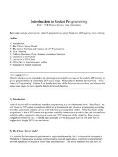
5 LGA775 Handling & System IntegrationSocket Handling Overview & RecommendationsSocket Preparation, Package Insertion, Package RemovalTIM Application & RemovalVisual Inspection: Contact Damage & Inspection FlowAgenda5 Contact Array Metal contacts Susceptible to mechanical damageLoad Plate Distributes uniform load to LGA, ensuring electrical connection between Package pads and Socket contactsLoad LeverSocket Body Integral to the DSL mechanism Contains Package orientation keys Not removable Aligns the Package Finger cutoutsPick and Place (PnP) Cap Protects Socket contacts Varies according to supplierLGA Socket Technology Overview: LGA Socket Features1 Pictures for illustration onlyOrientationKeysLoadLeverLoad PlateContact ArrayPnPCapSocket Body6 LGA Package Technology Overview.
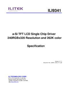
6 LGA Package & Shipping MediaKey Attributes x Package Stepped Integrated Heat Sink (IHS) for Socket Load Plate interface Land Grid Array (no pins, exposed land pads), gold pads Notched substrate for orientation control Shipping Media: Thermoformed trays Land Side Cover (LSC) to protect LGA Package land pads from scratches and contamination when handled with vacuum wand or by handLGA Package in Thermoformed TrayLand Side CoverAvoid touchinggold pads!Note: LGA packages dropped with or without the land side cover should be Pads7 Key emphasis areas Packages are nearly identical, but uniquely keyed Differences are difficult to see to the untrained eye- potential for misidentification Inventory can easily be mixed on lines that build with both LGA771 & LGA775 based products Understand Package labeling and keying relative to pin 1 to avoid of LGA775 vs.
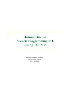
7 LGA771 LGA 771 LGA775 Manufacturing ConsiderationsPackageLands771775 Different Intel enabling components solutionKeyingFeature2 cut outs on upper X axis2 cut outs on left y axisDesign for orientation controlTypical Product SegmentServerDesktopDifferentiate between Server and Desktop solutions8 Comparison of LGA775 Vs LGA771 Pin 1 Triangle MarkingsLGA775 LGA771 LGA775 LGA771 Orientation NotchesOrientation Notches9 Comparison of LGA775 vs. LGA771 sockets with ProcessorSockets without ProcessorLGA771 LGA771 LGA775 LGA77510 LGA771 Package & SocketPin 1 referenced to Package notchPin 1 Triangle MarkingsOrientation NotchesNo Notch!
8 Pin 1 LocatorSocket Keying Feature11 LGA775 Package & SocketPin 1 referenced to Package notchOrientation NotchesPin 1 Triangle MarkingsSocket Keying Features12 Socket Platform Handling: ESD SensitivityStandard ESD handling practices should be should only be unpacked from boxes at ESD workstations All persons handling processors should be properly grounded. All work and storage surfaces for processors should be properly grounded. All tools and equipment used to install or rework processors should be properly proper storage and material transfer Transfer material using ESD safe trays, not by hand Remove processors from trays when they are ready to be used Units should be handled by the substrate edge For more information on ESD, visit Intel s website at: Handling RecommendationsDo not touch Socket contacts or processor land padsDo not push on center of PnP cap to remove- instead, use the cap tab to handleAvoid incorrect CPU orientationNon-Recommended Manufacturing Practices.
9 The following are examples of activities known to cause damage or quality failures 14Do not insert CPU in a tilted fashionDo NOT close lever without DSL tab engaged during assemblyDo NOT remove PnP cap before opening the load plateSocket Handling RecommendationsNon-Recommended Manufacturing Practices (cont): 15 From CPU1. Grasp and hold CPU by substrate edge2. Lint and other loose particulates can be removed using oil-free, low pressure compressed air (follow local safety regulations)3. Wet lint-free cloth with IPA and wipe Package land pads lightly to remove FM Limit contact to contaminated area only Use a daubing motion to minimize scoring and avoid spreading FMNote: All operations using IPA should be accomplished with latex gloves4.
10 Repeat with a clean cloth each time until no FM is visible (w/out magnification) If cleaning is unsuccessful, CPU must be scrapped5. If FM is Thermal interface Material (G751) or Flux: Allow Package to sit for 5-10-minutes after Step 3 Inspect under 10x magnification Presence of FM under magnification is unacceptable, except per below condition, repeat step 1 : Presence of FM in micro-vias is ok. Attempt to remove FM from micro-vias by using any sharp implement is not recommended. This could result in non-repairable CPU damageFrom SocketOil-free low pressure air can be used to blow off loose particles (Follow local safety regulations) on Socket : IPA may be dripped onto the Socket to remove or dissolve FM.